News & Views, Volume 49 | Inspection Optimization: Probabilistic Fracture Mechanics
By: Scott Chesworth (SI) and Bob Grizzi (EPRI)
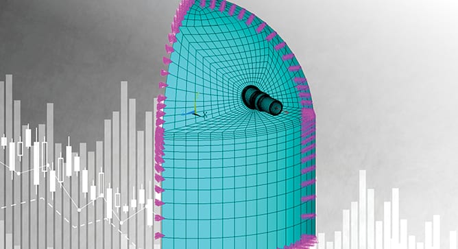
The goal was to determine whether the frequency of current inspection requirements was justified or could be optimized (i.e., increase the interval of certain inspections to devote more attention to higher-value inspections and thereby maximize overall plant safety).
Executive Summary
Welds and similar components in nuclear power plants are subjected to periodic examination under ASME Code, Section XI. Typically, examinations are performed during every ten-year inspection interval using volumetric examination techniques, or a combination of volumetric and surface examination techniques. Nuclear plants worldwide have performed numerous such inspections over plant history with few service induced flaws identified.
SI was selected by the Electric Power Research Institute (EPRI) to review the technical bases for the inspection intervals for select components. The goal was to determine whether the frequency of current inspection requirements was justified or could be optimized (i.e., increase the interval of certain inspections to devote more attention to higher-value inspections and thereby maximize overall plant safety.)
An inspection interval review takes into consideration industry operating experience (OE), operating history and previous inspection data. Many of the components / welds are difficult to access (require scaffolding and removing insulation), require manual techniques of inspection, and are typically in high radiological dose areas. The inspections can also have significant impact to outage duration. Reducing the frequency of inspections has the potential for time and cost savings during outages and reduces the radiation exposure to plant personnel. From the inspection interval review, one utility noted that increasing the inspection interval for steam generator nozzle welds from 10 years to 30 years would save over $600,000 of inspection and supporting activity costs over a 60-year licensed period of operation. Actual savings for a given plant are situation-dependent, although the potential for significant Operations and Maintenance (O&M) savings exists.
Background
To identify which components and inspection requirements were most suitable for optimization, EPRI performed an initial scoping investigation to collect the following information:
- The original bases for the examinations, if any;
- Applicable degradation mechanisms, and the potential to mitigate any potential damage associated with each mechanism;
- Operating experience, examination data, and examination results, e.g., fleet experience;
- Previous relief requests submitted to regulators;
- Industry guidance documents that replace or complement ASME Code requirements;
- Redundancy of inspections caused by other industry materials initiatives and activities (e.g., Boiling Water Reactor Vessel and Internals Project (BWRVIP), Materials Reliability Program (MRP), etc.); and
- Existing ASME Code Cases that provide alternatives to existing ASME Code inspection requirements and their bases.
After compilation and review of the information collected, EPRI and their members determined that the inspection requirements for the following components were among the most suitable for optimization:
- Pressurized water reactor (PWR) steam generator shell and nozzle welds and nozzle inside radius sections;
- PWR pressurizer shell and nozzle welds; and
- Boiling water reactor (BWR) heat exchanger shell and nozzle welds and nozzle inside radius sections.
Once the components were identified, EPRI contracted with SI to support development of the technical bases to optimize the related inspections. These evaluations are documented in the following four EPRI reports, all of which are publicly available for download at www.epri.com:
- Technical Bases for Inspection Requirements for PWR Steam Generator Feedwater and Main Steam Nozzle-to-Shell Welds and Nozzle Inside Radius Sections, EPRI, Palo Alto, CA: 2019. 3002014590.
- Technical Bases for Inspection Requirements for PWR Steam Generator Class 1 Nozzle-to-Vessel Welds and Class 2 Vessel Head, Shell, Tubesheet-to-Head, and Tubesheet-to-Shell Welds, EPRI, Palo Alto, CA: 2019. 3002015906.
- Technical Bases for Inspection Requirements for PWR Pressurizer Head, Shell-to-Head, and Nozzle-to-Vessel Welds, EPRI, Palo Alto, CA: 2019. 3002015905.
- Technical Bases for Examination Requirements for Class 2 BWR Heat Exchanger Nozzle-to-Shell Welds; Nozzle Inside Radius Sections; and Vessel Head, Shell, and Tubesheet-to-Shell Welds, EPRI, Palo Alto, CA: 2020. 3002018473.
Why It Matters
Recent efforts in the nuclear industry include a focus on reducing the cost of generating electricity to make nuclear more competitive with other sources (natural gas, etc.). A major component of these efforts is a targeted reduction of plant O&M costs, while ensuring that there is no detrimental impact on plant safety. Reducing low-value (i.e., low-risk, high-cost) inspections allows plant resources to be devoted to higher value activities (e.g., preventative maintenance). This is one benefit of employing risk-informed approaches.
The industry (in conjunction with EPRI, SI, and others) has shown a great deal of interest in employing risk-informed approaches where appropriate. Such efforts include (but are not limited to):
Extremely Low Probability of Rupture (xLPR)
- ASME Code Case N-702 (alternative requirements for BWR nozzle inner radius and nozzle-to-shell welds)
- ASME Code Case N-711 (volume of primary interest)
- ASME Code Case N-716-1 (streamlined risk-informed inservice inspection)
- ASME Code Case N-752 (risk-informed repair / replacement)
- ASME Code Case N-770-6 (cold leg piping dissimilar metal butt weld inspection)
- ASME Code Case N-864 (reactor vessel threads in flange examinations)
- ASME Code Case N-885 (alternative requirements for interior of reactor vessel, welded core support structures and interior attachments to reactor vessels, and removable core support structures)
- ASME Code Case N-[xxx] (alternative requirements for pressure-retaining bolting greater than 2 inches in diameter)
- 10CFR50.69 (risk-informed categorization and treatment of systems, structures, and components)
- The inspection optimization approach discussed here is congruent with these other approaches, as it uses probabilistic and risk insights to help plants to prioritize inspection and maintenance activities on those components most significant to plant safety.
How It’s Done
In the four EPRI reports cited above, the technical basis for increasing the interval of components inspections included the following steps:
- Review of previous related projects
- Review of inspection history and examination effectiveness
- Survey of components and selection of representative components for analysis
- Evaluation of potential degradation mechanisms
- Component stress analysis
Once the above steps were completed, components are subjected to Deterministic and Probabilistic Fracture Mechanics Evaluations. The DFM and PFM approaches used in the EPRI reports are based on methods used in previous inspection optimization projects, and involved either an increase in examination interval, a reduction in examination scope, or both. The DFM evaluations were performed using bounding inputs to determine the length of acceptable component operability with a postulated flaw. The results of the DFM investigation were also to determine the critical stress paths for consideration in the PFM analyses. The results of the DFM evaluations concluded that all selected components are very flaw tolerant, with the capability of operating with a postulated flaw for more than 80 years.
PFM evaluations were performed to demonstrate the reliability of each selected component assuming various inspection scenarios (e.g., preservice inspection (PSI) only, PSI followed by 10-year in-service inspections (ISI), etc.). Monte Carlo probabilistic analysis techniques were used to determine the effect of randomized inputs and various inspection scenarios on the probabilities of rupture and leakage for the selected components. Sensitivity studies are performed to investigate possible variation in the various input parameters to establish the key parameters that most influence the results.
For each component, probabilities of rupture and leakage were determined for the limiting stress paths in each selected component for a variety of inspection scenarios. The results of the PFM evaluations demonstrated that the NRC acceptance criteria of 1.0E-6 for both probabilities of rupture and leakage could be maintained for all components for inspection intervals longer than the 10-year intervals defined in Section XI of the ASME Code. Therefore, the results demonstrate that examinations for the selected components can be extended beyond current the ASME Code-defined interval; in some cases, they can be extended out to the end of the current licensed operating period (at least 30 years for most plants).
Why Structural Integrity
SI is the primary author of the four EPRI Reports cited above (3002014590, 3002015906, 3002015905 and 3002018473). The inspection optimization projects have provided SI with the opportunity to use its experience in structural reliability to develop a customized PFM software tool named PROMISE (PRobablistic OptiMization of InSpEction), which was used to optimize the inspection schedules for various plant components. The PROMISE software implemented a probabilistic model of fatigue crack growth using linear elastic fracture mechanics (LEFM) methods, consistent with ASME code, Section XI flaw evaluation procedures.
The software was developed, verified & validated (V&V), and tested under the provisions of a 10 CFR 50, Appendix B Nuclear Quality Assurance Program. This tool is based on other, similar previous software codes, and it can be used for similar applications in the nuclear industry where a rigorous technical basis is required to optimize inspection schedules for high-reliability components involving significant outage impact. In 2020, the NRC staff conducted an audit of PROMISE. According to the conclusion of the audit report (ML20258A002), the NRC staff gained a better understanding of how PFM principles were implemented in PROMISE and of the V&V on the software.
In addition to the software audit, SI has supported EPRI and industry in developing responses to NRC requests for additional information (RAIs) for the pilot plant submittals for all four EPRI Reports. This experience has given SI a great deal of understanding regarding the most efficient and effective way to preemptively address potential NRC concerns in future plant-specific submittals.
How It Would Work For You
For plant owners to use the technical bases established by this work to obtain relief for their plant, they must demonstrate that the representative geometries, materials, and loading conditions used for the selected components bound their plant-specific information. Based on this analysis, the EPRI Reports provide criteria for each component regarding the component configuration, component dimensions, component materials, applicable transient loadings, and other relevant parameters that must be satisfied on a plant-specific basis. If all criteria are satisfied on a plant-specific basis for a given component, the results of the investigation can be used for the plant as the technical basis to establish revised inspection schedules for that component. If any criteria are not satisfied, then plant-specific analysis is required to address any unbounded conditions. SI can provide support in several areas, including:
Since the technical basis in the EPRI Reports used generic plant configurations, some plant configurations were not included in the analysis. SI can also support efforts by plants with such configurations to determine whether they are bounded by the criteria of the EPRI Reports.
- Evaluation of plant-specific parameters against report criteria to determine whether a given plant configuration is bounded
- Performing plant-specific analysis (e.g., component stress analysis, DFM and PFM, etc.) required to address any unbounded conditions
- Supporting development of the relief request to proactively address known NRC areas of concern
- Supporting development of responses to any NRC requests for additional information
Plant Experience To Date
The first plant-specific submittal was made by a U.S. two-unit PWR site in December 2019 based on EPRI Report 3002014590, requesting an inspection alternative to current ASME Code, Section XI examination requirements for steam generator main steam and feedwater nozzle-to-shell weld and inner radii examinations. The alternative requests an increase in the inspection interval for these items from 10 to 30 years. The safety evaluation report (SER) for this alternative was received from the NRC in January 2021.
The first plant-specific submittal was made by a U.S. PWR site in December 2019 based on EPRI Report 3002015906, requesting an inspection alternative to current ASME Code, Section XI examination requirements for steam generator Class 1 nozzle-to-vessel welds and Class 2 vessel head, shell, tubesheet-to-head, and tubesheet-to-shell welds. The alternative requests an increase in the inspection interval for these items from 10 to 30 years. RAIs for this alternative were received from the NRC in February 2021. SI supported development of the RAI responses.
The first plant-specific submittal was made by a U.S. two-unit PWR site in December 2019 based on EPRI Report 3002015905, requesting an inspection alternative to current ASME Code, Section XI examination requirements for Pressurizer Head, Shell-to-Head, and Nozzle-to-Vessel Welds. The alternative requests an increase in the inspection frequency for these items from 10 to 30 years. RAIs for this alternative were received from the NRC in February 2021. SI supported development of the RAI responses.
The first plant-specific submittal was made by a U.S. two-unit BWR site in December 2019 based on EPRI Report 3002018473, requesting an inspection alternative to current ASME Code, Section XI examination requirements for Class 2 BWR heat exchanger nozzle-to-shell welds; nozzle inside radius sections; and vessel head, shell, and tubesheet-to-shell welds. The alternative requests an increase in the inspection interval for these items from 10 years to the end of the plant’s current operating license. RAIs for this alternative were received from the NRC in February 2021. SI supported development of the RAI responses.
Conclusion
Inspection optimization offers the opportunity to reallocate plant resources to higher value activities. In a highly competitive electricity market, the work here has shown opportunity exists to improve O&M costs and maintain safety through effective analysis.
SI brings to bear the prior experience in developing the methodology with EPRI, proprietary NQA-1 verified software, and decades of industry credibility to support all aspects of the efforts required to institute a program of inspection optimization.



 By: Sasan Etemadi, P.E. and Mark Drucker, P.E.
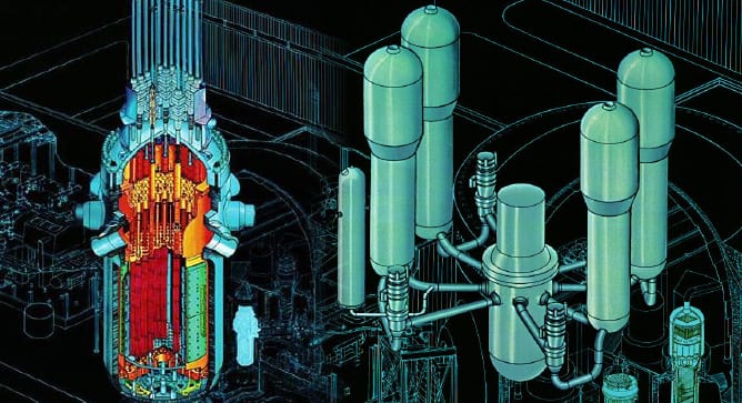 There have been several industry initiatives to support optimization of examination requirements for various items/components (both Class 1 and Class 2 components) in lieu of the requirements in the ASME Code, Section XI.
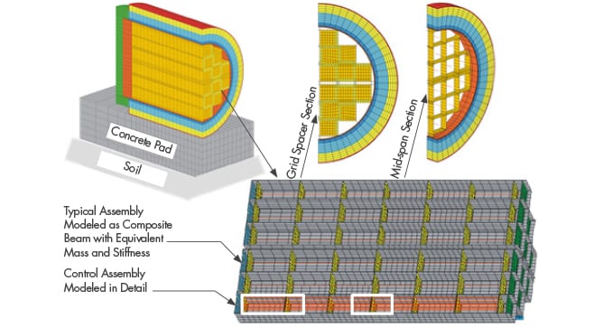 Structural Integrity Associates is participating in a Department of Energy (DOE) Integrated Research Projects (IRP) program focused on storage and transportation of used nuclear fuel (UNF). The project, entitled Cask Mis-Loads Evaluation Techniques, was awarded to a university-based research team in 2016 under the DOE Nuclear Fuels Storage and Transportation (NFST) project. The team is led by the University of Houston (U of H) and includes representatives from the University
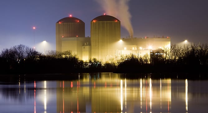 Nuclear power plants around the world are approaching the end of their original 40-year design life.
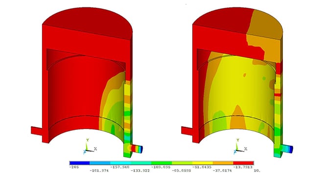 As part of the general design criteria for nuclear power plants, the primary structures and systems of the plant must be designed to handle postulated accident events, including the dynamic effects of postulated pipe ruptures. For a Boiling Water Reactor, analyzed events include various accident conditions in the recirculation piping, including a Loss of Coolant Accident (LOCA). One postulated LOCA event is assumed to be an instantaneous double-ended guillotine break of the recirculation line. This event causes several loads to be imparted on the reactor vessel, attached piping, and reactor internal components. [Some loads such as jet impingement, annulus pressurization, and pipe whip impart loads on the outside of the reactor vessel and the attached piping.][ Other loads, including flow-induced drag and acoustic loads, transmit loads inside the vessel on critical components such as jet pumps, core shroud, and the shroud support structure.] Figure 1 shows the pipe and resulting loads.