News and Views, Volume 54 | Analysis of Ultrasonic Pipe Cleaning and Viability for Use in Nuclear Power Plants
By: Ashkan Nejad, Ph.D.
Ultrasonic cleaning is a non-destructive, low-cost technological method that uses high-frequency waves to remove contaminants from materials. The process utilizes specialized ultrasonic devices equipped with transducers that emit longitudinal and flexural waves at frequencies ranging from 15 kHz to 25 kHz to dislodge contaminants and carry them away with a cleaning solution. Cleaning pipes using this method, in accordance with regulation and safety standards, would safely and effectively reduce maintenance costs while ensuring optimal pipe functionality. When applied in the nuclear industry, this technique also allows for reduced contamination and radiation dose.
Structural Integrity has performed a study and multi-faceted analysis of this technique and its effect on pipe stresses caused by the induced vibrations to determine the feasibility of using ultrasonic vibration waveforms to clean internal piping in nuclear power plants.
FORCED FLEXURAL VIBRATION IN PIPES
The field of piping dynamics focuses on analyzing the stress caused by vibrations in pipes. This involves the use of established beam theories, such as Rayleigh and enhanced Timoshenko beam theories, which have been extensively studied. These theories are used to create piping dynamics models that assess the free vibration and bending stress within the pipe. However, in cases of forced vibration, the stress distribution on the pipe’s thickness due to external forces extends into three dimensions, while advanced beam theories can only model the flexural stress distribution in two dimensions. Although these theories are useful in analyzing pipe vibration responses in low-frequency vibration modes, they are inadequate for steady-state high-frequency harmonic loads on the pipe.
Experimental dynamic stress analysis is expensive and faces challenges when dealing with high-frequency flexural wavelength and instrumentation dimensions. Additionally, variations in pipe diameter and controlling voltage can significantly alter the dynamics of the ultrasonic resonator and pipe dimensions.
Despite these challenges, recent advancements in computational techniques and high-speed computers have made modeling elastic flexural wave propagation in piping systems more attainable. Accordingly, this study employs linear dynamics finite element (FE) analysis to simulate the flexural stress wave propagation in two ultrasonic resonator devices attached to a stainless-steel pipe. The subsequent extraction of three-dimensional stress and linearization stress distribution facilitates the evaluation of peak and bending stress as alternating stress. This analysis is then compared with the endurance limit, establishing a framework for qualifying the utilization of ultrasonic cleaning devices in nuclear plant piping systems.
STRESS LINEARIZATION
The Stress Linearization tool in the ANSYS program is used to separate stresses within a section into constant (membrane), linear (bending), and peak components. This option works by using a path defined by two nodes that traverse the thickness of the pipe cross-section. The path includes two endpoints, the coordinates of the cross-section (nodes), and 47 intermediate points automatically determined through linear interpolation in the active display coordinate system. Both start and end nodes are typically assumed to be located at free surfaces with the highest local equivalent stress intensity.
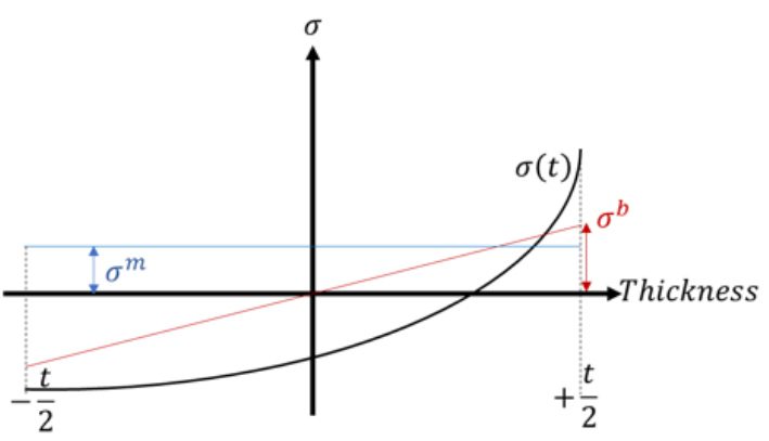
Figure 1. linearized stress distributions throughout the pipe thickness.
To calculate the membrane values of the stress components, an averaging integral is used across the thickness, with the centerline situated at the midpoint of the pipe thickness. Figure 1 shows the linearized stress distributions throughout the thickness, with the center of thickness as the coordinate center. The normalized bending stress can be compared with the allowable stress endurance defined in ASME OM3, but only for low-frequency modes where the bending stress is the dominant alternating stress. However, in high-frequency forced vibration, the stress distribution caused by shell-mode flexural waves through the thickness and longitudinal directions is approximately three-dimensional around the external force locations and two-dimensional far from the applied force location. This can make the peak alternating stress higher than the bending stress. Therefore, for comparison with allowable stress, peak stress should be considered as a conservative method. This approach ensures a comprehensive assessment of stress distribution and facilitates a nuanced analysis of constant and linear stress components within the specified section.
FORCED HARMONIC EXCITATION AND RESPONSE
When the ultrasonic resonator has voltage applied, with a frequency sweep from 21 to 22.5 kHz, this results in the harmonic displacement of the piezoelectric disks. The displacement then travels through the contacts between the ultrasonic cleaning component and the pipe. To analyze the equation of motion, the Harmonic Full Method is used. The Full Method involves solving a system of simultaneous equations directly using a Sparse matrix solver designed for complex arithmetic, Equation (1). This static complex form is derived from the forced equation of motion shown in Equation (2). The I and R subscripts in Equation (2) show the real and imaginary components of the complex vectors. The method accommodates various loads and boundary conditions. It also incorporates the effects of inertia and damping components to obtain the forced vibration displacement response. A conservative damping coefficient of 0.5% is used to simulate energy dissipation in the material through hysteretic damping. The calculated displacement is
The stress intensity is calculated, which is twice that of Shear Tresca. Afterward, it is linearized and compared with the allowable stress limitations. This methodology accurately assesses the resonator’s dynamic response and its implications on stress levels. It provides conservative insights into the structural performance under harmonic excitation.
SI’s RESULTS
SI conducted studies and analyses to find the benefits of using ultrasonic vibration waveforms to clean internal piping in nuclear power plants to enhance flow dynamics and reduce radiation exposure. The ASME Code for Operation and Maintenance of Nuclear Power Plants was followed to monitor pipe vibrations, and computational tools such as finite element analysis were utilized to assess piping responses to dynamic loads induced by ultrasonic transducers.
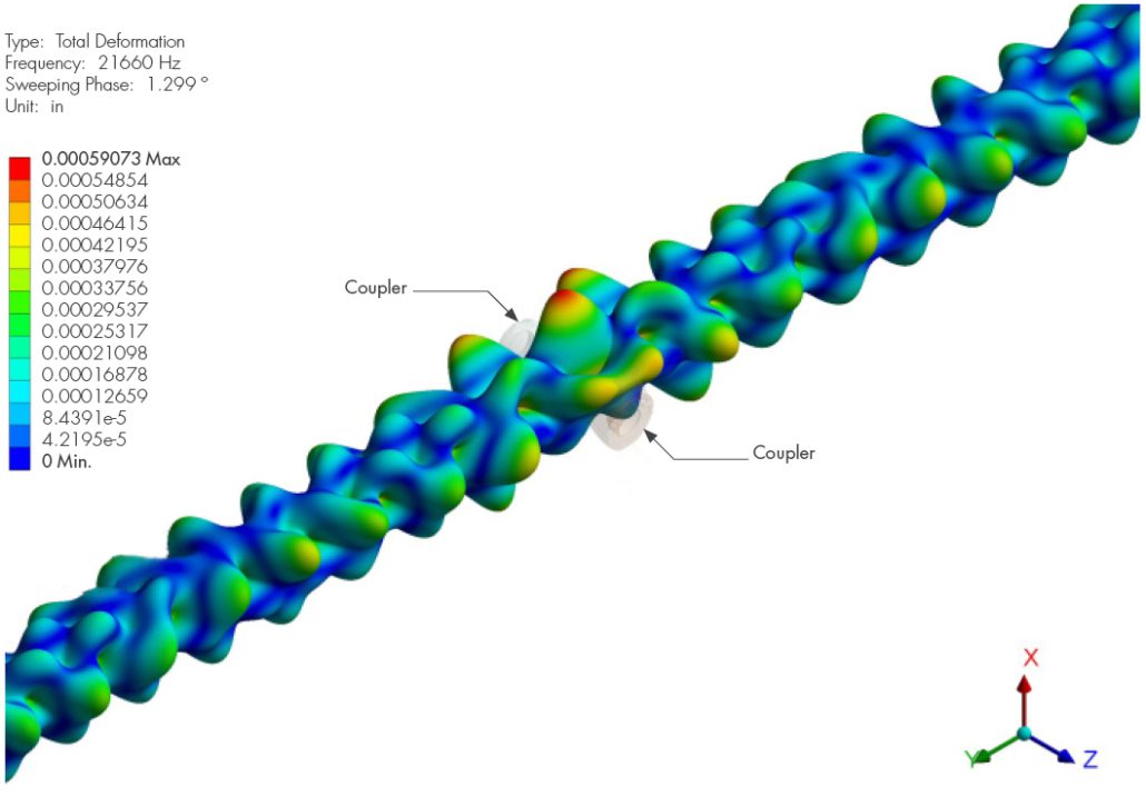
Figure 2. Displacement Harmonic response of pipe under high-frequency transducer loading through the Couplers.
Based on our findings, SI proposes a new approach that utilizes linearized stress intensity derived from finite element linear dynamics analysis tools. This approach offers a more conservative estimate of allowable alternating peak stress values compared to relying solely on bending stresses. This method addresses the limitations of linearized alternating bending stress in accurately calculating stress under high-frequency harmonic loads, where shear waves and shell modes are induced.
Our research confirms the efficacy of linearized peak stress as a superior metric for evaluating stress-induced fatigue in high-frequency ultrasonic cleaning applications.


