
Structural Integrity Associates Acquired by MidOcean Partners
SAN JOSE, CA – August 15, 2024 – SI Solutions today announced their acquisition by
SAN JOSE, CA – August 15, 2024 – SI Solutions today announced their acquisition by
COMPONENT ASSESSMENT AND ANALYSIS By John Molloy Structural Integrity (SI) has decades of experience dealing
By Kane Riggenbach and Eric Jones Background The power generation industry has seen an increasing
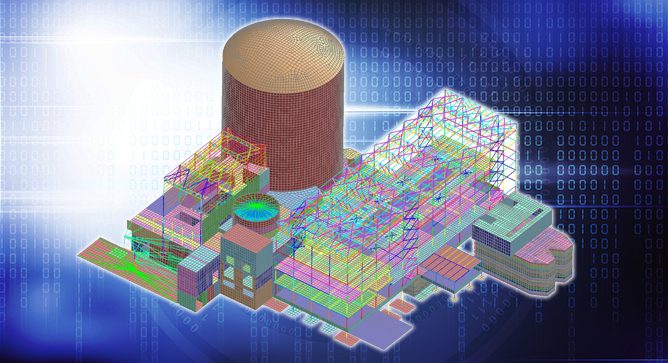
By Julio Garcia, PhD, PE Abstract Continued advances in the fields of structural and geotechnical
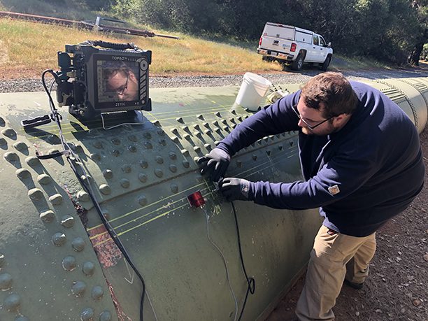
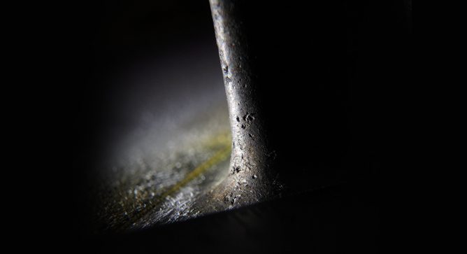
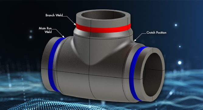
By: Jason Van Velsor and Jeff Milligan At SI, we regularly combine advanced NDE inspections

CHARLOTTE, NC – SI Solutions is pleased to announce the purchase of SC Solutions, Inc.,
Strain-Induced Precipitation Hardening, also known as SIPH, is a commonly misinterpreted boiler tube failure mechanism

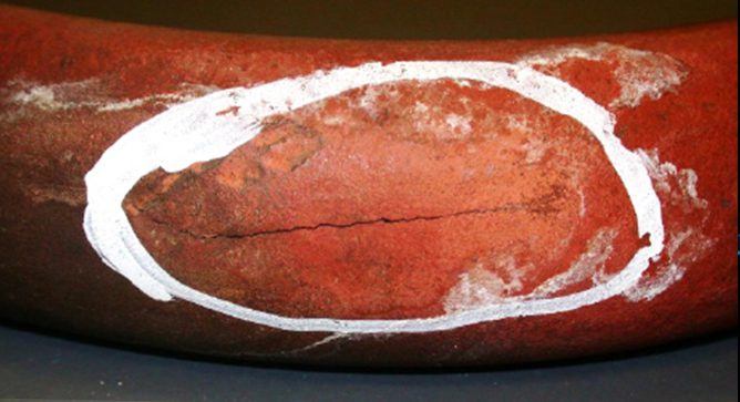
By: Terry Totemeier A client recently ordered a Type 316 stainless steel pipe coupling fitting
At Structural Integrity Associates (SIA), we take cybersecurity very seriously for ourselves and our clients,
Structural Integrity Associates, Inc. (SIA) is pleased to announce the addition of Daniel (Dan) Patten