News and Views, Volume 55 | UPDATE: Encoded Phased Array Ultrasonic Examination Services for Cast Austenitic Stainless Steel (CASS) Piping Welds in Pressurized Water Reactor (PWR) Coolant Systems
By: John Hayden and Jason Van Velsor
Our initial article on this topic in News & Views, Volume 531 describes the challenges imposed by cast austenitic stainless steel (CASS) materials and the development of our CASS UT Examination solution. At the time of the prior article’s publication, SI was also conducting examinations of numerous CASS piping specimens. This article provides details of both that performance demonstration and the results of those examinations.
TYPICAL CASS PIPING WELD LOCATIONS IN PWR REACTOR COOLANT SYSTEMS
Figure 1 illustrates the presence of CASS piping components, both statically and centrifugally cast, in the primary Reactor Coolant Systems of many U.S. PWR plants. Other PWR plant designs also contain CASS components, albeit in fewer locations and only in the form of short spool piece segments, usually for reactor coolant pumps and safety injection system safe ends.
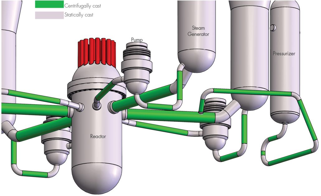
Figure 1. Locations of CASS piping components, both statically and centrifugally cast, in primary Reactor Coolant Systems of many U.S. PWR plants
REGULATORY BASIS FOR CASS EXAMINATION CAPABILITY
ASME Section XI Code Case N-824, which was approved by the NRC in 2019, provides specific direction and requirements for ultrasonic examination of welds joining CASS components. N-824 was incorporated into Section, XI, Appendix II, Supplement 2 in the 2015 Code edition. The NRC has stated (10CFR50.55a, 07/18/2017) that with use of the aforementioned N-824 methodology “Licensees will be able to take full credit for completion of the § 50.55a required in-service volumetric inspection of welds involving CASS components.” SI’s procedure development and demonstration were therefore based on these requirements.
ULTRASONIC TECHNIQUE PERFORMANCE DEMONSTRATION
Though not required by the ASME Code, SI conducted a performance demonstration of our CASS UT system at our facility in Huntersville, NC. Using CASS piping system specimens on loan from the EPRI NDE Center, SI successfully validated our ultrasonic examination system capabilities as follows.
Ultrasonic Procedure – SI’s CASS ultrasonic examination procedure is fully compliant with ASME Section XI Code documents, and NRC-imposed technical approval conditions. The procedure has also been optimized with many insights gained from our laboratory experiences while examining EPRI-owned CASS piping specimens.
Ultrasonic Equipment – The ultrasonic system components required by Code have been designed and fabricated by SI or purchased, including the following:
- Ultrasonic instrumentation capable of functioning over the entire prescribed ranges of examination frequencies. The standard examination frequency range extends from low-frequency, 500 KHz operation for CASS pipe welds > 1.6” Tnom and 1.0 MHz for CASS pipe welds ≤ 1.6” Tnom
- Transducer arrays were employed to meet the physical requirements of frequency and aperture size capable of generating the Code-prescribed wave mode, examination angles, and focal properties.
- An assortment of wedge assemblies were designed and fabricated then mated with transducer arrays to provide effective sound field coupling to the CASS components being examined.
Data encoding options necessary to acquire ultrasonic data given the expected range of component access and surface conditions are available. The encoding options include:
- A fully-automated scanning system capable of driving the relatively large and heavy 500KHz phased array probes. This system was used during our laboratory examinations of CASS piping specimens.
- A manually driven encoding system — a proven, field-worthy tool — which may be employed in locations where fully automated systems cannot be used because of access restrictions.
Examination Personnel – The challenges that exist with the examination of CASS piping welds warrant a comprehensive program of specialized, mandatory training for personnel involved with CASS examinations. This training includes descriptions of coarse grain structures, their effect on the ultrasonic field, the expected ultrasonic response characteristics of metallurgical and flaw reflectors, and the evaluation of CASS component surface conditions.
Additionally, SI’s ultrasonic examination personnel are thoroughly trained and experienced in all elements of encoded phased array ultrasonic data acquisition and analysis in nuclear plants and hold multiple PDI qualifications in both manual and encoded phased array DM weld techniques.
EPRI CASS PIPING SPECIMENS
The EPRI CASS pipe specimens, their outside diameter (OD) and thickness dimensions, and butt weld configurations examined by SI are described below.
12.75″ OD, 1.35″ Tnom SPECIMENS
Three pipe-to-pipe specimens representative of piping found in pressurizer surge and safety injection applications were examined. Each of these specimens had the weld crown ground flush.
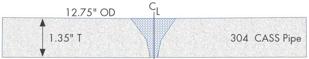
Figure 2. Schematic of 12.75” OD, 1.35” Tnom CASS specimens.
Figure 3, Figure 4, and Figure 5 present examples of ultrasonic data images of a flaw detected in a 12.75” OD pipe-to-pipe tapered specimen.
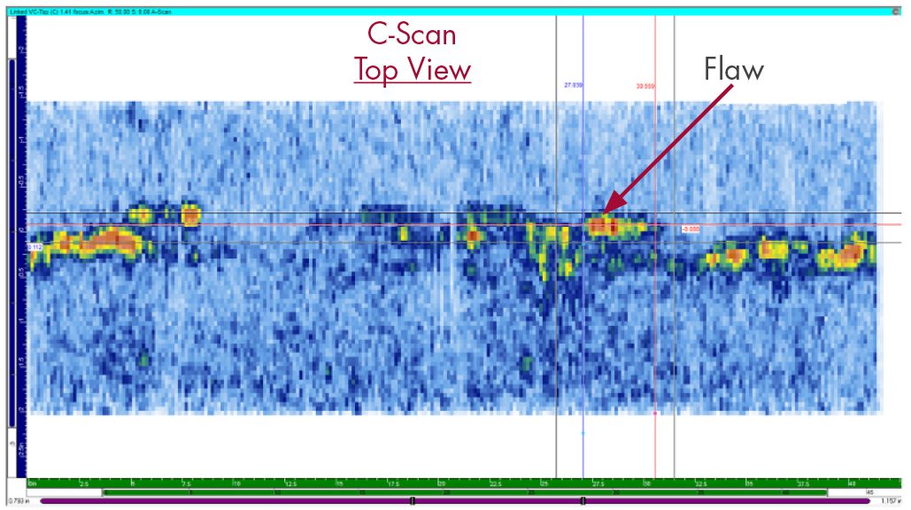
Figure 3. Representative ultrasonic C-Scan data image from 12.75” OD, 1.35” Tnom specimen.
The C-Scan is a 2-D view of ultrasonic data displayed as a top (or plan) view of the specimen. The horizontal axis is along the pipe circumference, and the vertical axis is along the pipe axis or length.
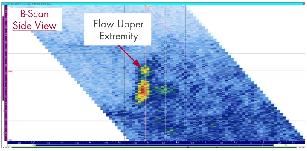
Figure 4. Representative ultrasonic B-Scan data image from 12.75” OD, 1.35” Tnom specimen.
The B-Scan is a 2-D view of ultrasonic data displayed as a side view of the specimen. The angular projection of the data is displayed along the examination angle. The horizontal axis is along the pipe axis, and the vertical axis is along the pipe thickness.

Figure 5. Representative ultrasonic D-Scan data image from 12.75” OD, 1.35” Tnom specimen.
The D-Scan is a 2-D view of ultrasonic data displayed as an end view of the specimen. The horizontal axis represents the pipe circumference, and the vertical axis is along the pipe thickness.
28″ OD, 2.0″ Tnom SPECIMENS
Four pipe-to-pipe specimens representative of piping found in reactor coolant loops were examined. Each of these specimens had the weld crown intact and left in place.
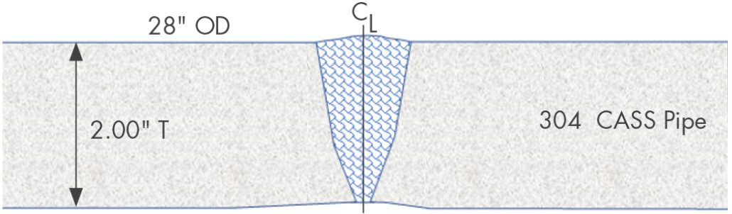
Figure 6. Schematic of 28” OD, 2.0” Tnom CASS specimens.
Figure 7, Figure 8, and Figure 9 present examples of ultrasonic data images of a flaw detected in a 28” OD pipe-to-pipe tapered specimen.
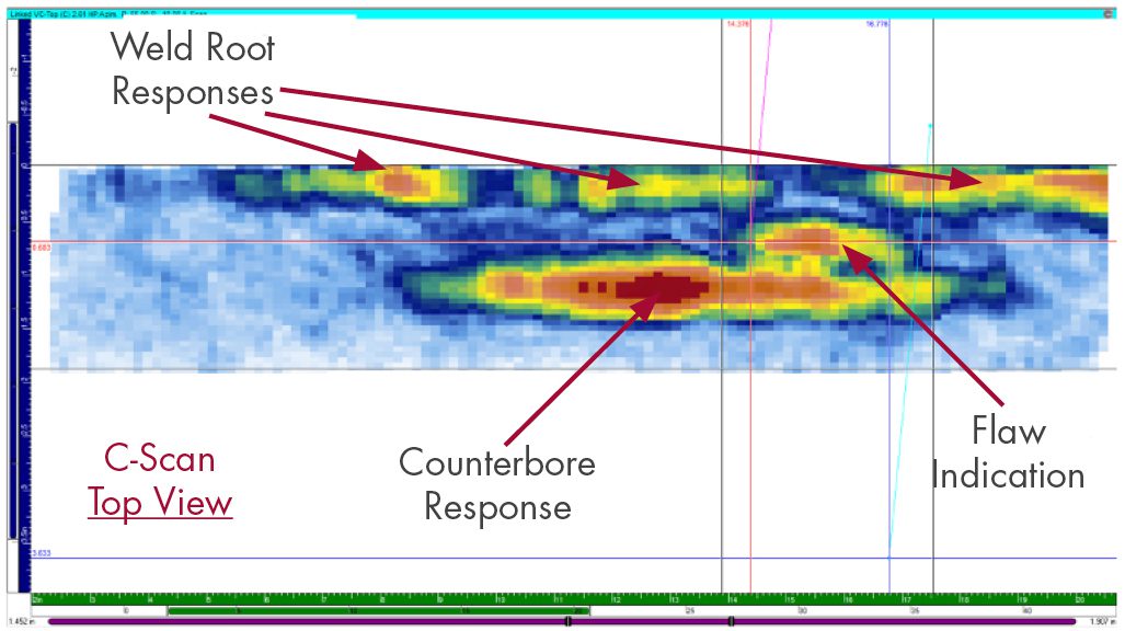
Figure 7. Representative ultrasonic C-Scan data image from 28” OD, 2.0” Tnom specimen.
The C-Scan is a 2-D view of ultrasonic data displayed as a top (or plan) view of the specimen. The horizontal axis is along the pipe circumference, and the vertical axis is along the pipe axis or length.
Note the ability of our UT data acquisition equipment and data analysis techniques to resolve, discriminate, and identify inside surface geometric conditions (weld root and pipe counterbore), along with detecting and sizing the flaw indication. Also, note the excellent signal-to-noise ratio achieved.
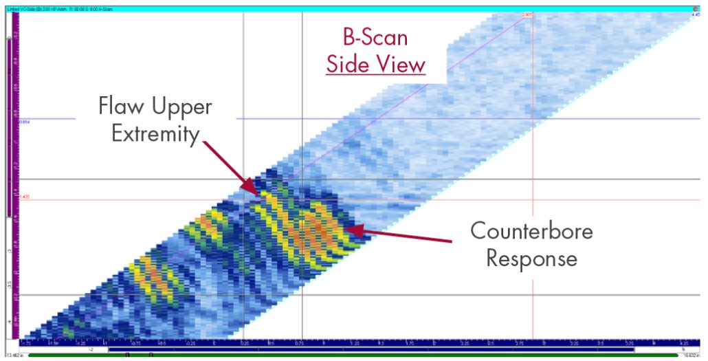
Figure 8. Representative ultrasonic B-Scan data image from 28” OD, 2.0” Tnom specimen.
The B-Scan is a 2-D view of ultrasonic data displayed as a side view of the specimen. The angular projection of the data is displayed along the examination angle. The horizontal axis is along the pipe axis or length. The vertical axis is along the pipe thickness.
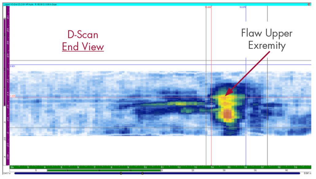
Figure 9. Representative ultrasonic D-Scan data image from 28” OD, 2.0” Tnom specimen.
The D-Scan is a 2-D view of ultrasonic data displayed as an end view of the specimen. The horizontal axis is along the pipe circumference, and the vertical axis is along the pipe thickness.
28″ to 29″ OD, 2.0″ to 2.5″ Tnom TAPERED WELD SPECIMENS
Four pipe-to-pipe specimens, with tapered weld surfaces representative of piping found in reactor coolant loops were examined.
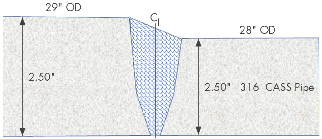
Figure 10. Schematic of 28” to 29” OD, 2.0” to 2.5” Tnom CASS specimens.
Figures 11, 12, and 13 present examples of ultrasonic data images of a flaw detected in a 28” OD to 29” OD pipe-to-pipe tapered specimen.
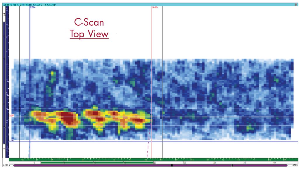
Figure 11. Representative ultrasonic C-Scan of a 28” to 29” OD, 2.0” to 2.5” Tnom pipe-to-pipe, with tapered weld surfaces.
The C-Scan is a 2-D view of ultrasonic data displayed as a top (or plan) view of the specimen. The horizontal axis is along the pipe circumference, and the vertical axis is along the pipe axis, or length.
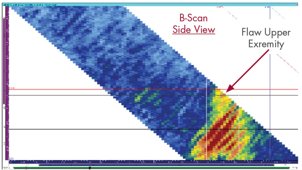
Figure 12. Representative ultrasonic B-Scan of a 28” to 29” OD, 2.0” to 2.5” Tnom pipe-to-pipe, with tapered weld surfaces.
The B-Scan is a 2-D view of ultrasonic data displayed as a side view of the specimen. The angular projection of the data is displayed along the examination angle. The horizontal axis is along the pipe axis or length. The vertical axis is along the pipe thickness.
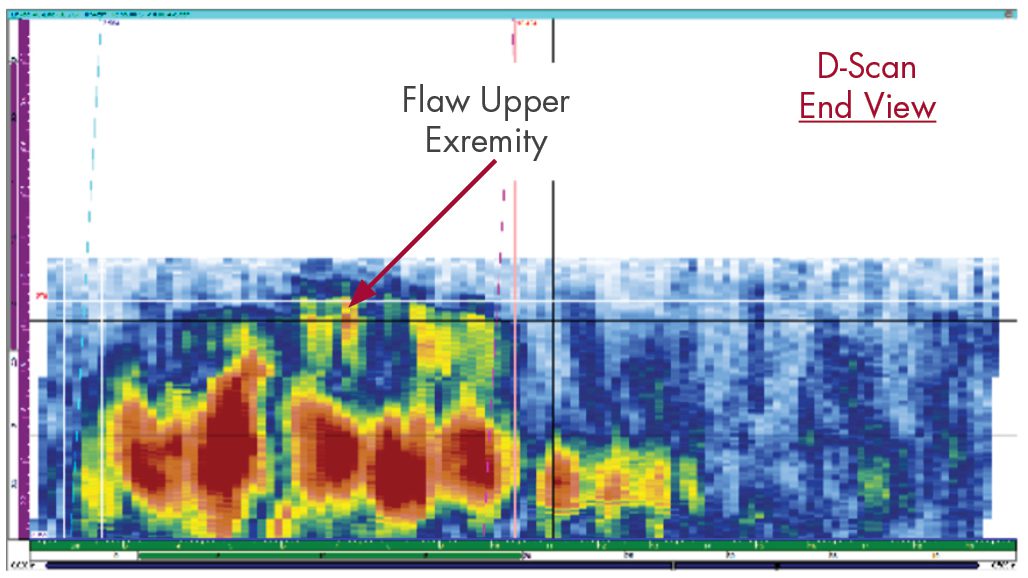
Figure 13. Representative ultrasonic D-Scan of a 28” to 29” OD, 2.0” to 2.5” Tnom pipe-to-pipe, with tapered weld surfaces.
The D-Scan is a 2-D view of ultrasonic data displayed as an end view of the specimen. The horizontal axis is along the pipe circumference, and the vertical axis is along the pipe thickness.
SUMMARY OF DATA ANALYSIS RESULTS
Documentation was provided for each EPRI specimen, which contains flaw location, length, and through-wall size to permit the comparison of UT data acquisition and analysis processes to actual flaw conditions.
All of the 23 circumferential flaws in the eleven EPRI specimens were detected. The ultrasonic examination and data analysis techniques achieved flaw location and length sizing RMS errors, which are within acceptance standards of the following ASME Section XI, Appendix VIII Qualification Supplements:
- Supplement 2, Qualification Requirements for Wrought Austenitic Stainless Steel Piping
- Supplement 10, Qualification Requirements for Dissimilar Metal Piping
Excellent signal-to-noise ratios were observed for all detected flaws.
For all flaws, the measured length achieved sizing RMS errors within the acceptance standards of the above Appendix VIII supplements.
For specimens with welds ground flush and for all specimens with sufficient access to interrogate the entire through-wall extent of flaws, SI’s technique achieved through-wall sizing RMS errors within the acceptance standards of the above Appendix VIII supplements.
To be clear, the examination of the EPRI CASS specimens does not meet the rigor of Appendix VIII, Supplement 9 qualification because the industry’s (PDI Program) for CASS piping welds is still in preparation. The comparison to Appendix VIII acceptance standards is provided solely as a means to describe the achieved flaw detection and sizing capabilities in CASS material in terms of already established PDI qualifications. Ongoing examination of additional CASS specimens will strengthen already existing ultrasonic examination capabilities and experience.
CONCLUSIONS
The CASS piping welds in many PWR plants provide numerous and complicated challenges to their effective ultrasonic examinations. Most, if not all, CASS RCS piping welds have not been subjected to a meaningful and effective volumetric examination since radiography was conducted during plant construction. SI’s newly-demonstrated ultrasonic examination procedure for CASS delivers a demonstrated, Code-compliant, meaningful, and effective solution that provides full credit for completion of in-service volumetric inspection per § 50.55a.
References
- News and Views, Volume 53, October 2023, “Encoded Phased Array Ultrasonic Examination Services for CASS Piping Welds In PWR Reactor Coolant Systems”
- ASME Section XI Code Case N-824, “Ultrasonic Examination of Cast Austenitic Piping Welds from the Outside Surface”
- ASME B&PV Code, Section XI, 2015 Edition and later editions


