News and Views, Volume 54 | Monticello Nuclear Generating Plant – BioShield Evaluation

By:  Livia Costa-Mello, Shari Day, and Dan Denis

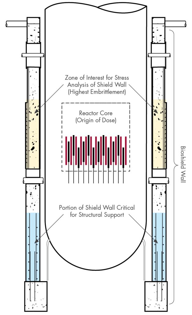
Figure 1. Example of RPV and Bioshield showing areas of interest for evaluation.

Background
Many U.S. nuclear plants are completing license renewal (LR) activities to extend their operating life.  The initial LR application extends operating licenses from 40 to 60 years; the subsequent renewal (SLR) further extends this from 60 to 80 years.  As part of the LR/SLR application process, utilities must demonstrate that they have accounted for a variety of potential aging mechanisms that may take place over the ensuing operating period.  One such mechanism is the loss of strength and/or ductility due to long-term exposure to high levels of radiation.  This includes the reactor pressure vessel (RPV) and primary system piping but also extends to support structures (steel/concrete) in the vicinity of the RPV.

Xcel Energy submitted their SLR application for the Monticello Nuclear Generating Plant in January 2023.  Constructed in the 1960s, Monticello is the oldest operating boiling water reactor (BWR) in the U.S. fleet and will reach 60 years of operation in 2030.  As part of the Nuclear Regulatory Commission’s (NRC’s) standard review plan (SRP) for SLR applications1, detailed evaluations are recommended for steel and concrete structures which are predicted to exceed certain established thresholds of irradiation dose.  This includes the biological shield wall (also referred to as the “bioshield” or “sacrificial shield”), a large concrete and steel structure that surrounds the RPV  whose primary purpose is to shield workers and equipment from high levels of neutron and gamma radiation.  In addition, the bioshield provides support for other critical components.

Xcel contracted SI to perform an evaluation of the Monticello bioshield in support of its SLR application.  Initially, SI assessed embrittlement of the concrete and steel in accordance with the methodology in NUREG-15092 .  Following questions posed by the NRC reviewers, additional clarifications were requested regarding plant-specific materials, justification of gamma heating parameters, and inclusion of weld residual stresses.  SI performed separate heat transfer and fracture mechanics analyses to address these inquiries.  This article summarizes the approach and results of this first-of-a-kind evaluation.

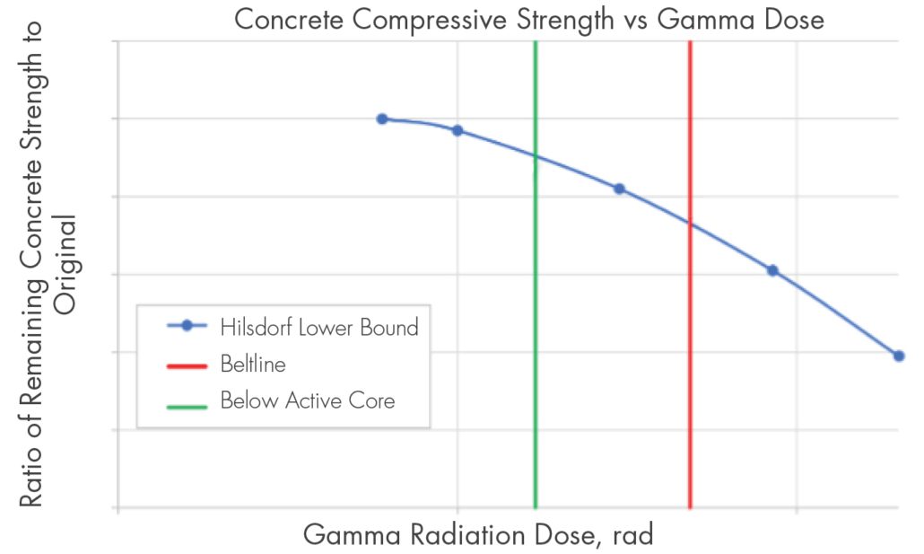
Figure 2. Typical Reduction in concrete strength due to irradiation.

Assessment of Bioshield Concrete Structure
As illustrated in figure 1, the portion of the shield wall that is critical for support purposes is near the bottom of the RPV, well below the active core.  However, in accordance with the SRP, the concrete within this region is evaluated for irradiation-induced capacity reductions in accordance with methodology outlined within related EPRI reports.  Both neutron and gamma dose were evaluated in accordance with NUREG-2192 guidelines, along with expected operating temperatures experienced by the concrete.

Radiation exposure levels for the Monticello bioshield at the end of the SLR operating period were computed via separate third-party analysis.  The computed neutron fluence was less than the threshold for potential concrete damage, rendering it unnecessary to evaluate this item, but the computed gamma dose exceeded the potential damage threshold.  Therefore, SI performed a detailed study to extrapolate the gamma exposure and any associated loss of strength for the load-bearing portion of the bioshield wall.  The evaluation compared published lower-bound strength values from literary sources to the fluence values obtained from which a conservative factor on reduction in structural capacity was determined.

SI performed a detailed set of structural calculations to benchmark the original design basis analysis against the pertinent code of construction, ACI 318-63.  These calculations were repeated for the predicted reduction in strength, and for all locations the predicted loads (or “demand”) were less than the available capacity.  Thus, the structural portion of the bioshield wall was assessed to be acceptable for extended operation through the SLR period.

Figure 3. Dpa Variation as a function of Distance from Core Mid-Plane, Adjusted to Bounding Dpa for Shield Wall

Assessment of Bioshield Steel Liner
SI performed an assessment of the steel liner plates on either side of the bioshield wall, in accordance with NUREG-1509.  The evaluation began with identifying the region of the bioshield subject to the highest radiation exposure.  Comparing the elevation of the active core to the predicted distribution of neutron irradiation, the region of interest was determined to be ±100 inches above/below the core centerline.  In this region, the only structural steel elements are the WF27x177 columns and the 1-¾” and ¼” thick liner plates.

For the indicated region, the effect of irradiation on the shift in ductile to brittle fracture transition temperature (known as “nil ductility temperature” or NDT) was evaluated.  An NDT shift is calculated by referencing the irradiation at various elevations against criteria from NUREG-1509; this value is added to the initial NDT to compute an adjusted NDT.

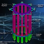
ANSYS was used to develop a finite element model of key structural members for subsequent analyses.  To benchmark the original design basis analysis, the model was initially developed using only the columns, girders, and stabilizers, after which all design basis loads were applied.  However, the results from this model were observed to exhibit significant displacement of the steel columns due to weak axis bending.  Therefore, SI developed an enhanced model for the key embrittled region to include the liner plates.  The maximum principal stresses from this enhanced model were demonstrated to be less than the 6 ksi operational stress limit in NUREG-1509.  Therefore, the steel portion of the Monticello bioshield was determined to remain structurally sound for the period of SLR extended operation.

Figure 4. Frame Model of Shield Wall Space Frame

Upon initial NRC review of the concrete and structural evaluations, additional questions were raised regarding NRC desired modifications to the NUREG-1509 methodology for extended SLR operation.  The primary focus of these questions related to conservatism of the analyses when accounting for Monticello-specific properties, such as gamma heating of the concrete and impacts of weld residual stresses.  Accordingly, SI developed a plant-specific heat transfer evaluation, and used those results to perform a fracture mechanics analysis of the stress state in the limiting beltline region.

Bioshield Heat Transfer Analysis
During NRC review of the steel and concrete analyses described in the prior sections, questions were raised regarding the potential for additional degradation of the concrete due to extended exposure to high temperatures and gamma-induced heating.  To address these questions, SI developed a heat transfer model of the bioshield, accounting for RPV insulation, the annular air gap, and conduction through both liner plates and the concrete.  Calculations were performed both by hand and using an axisymmetric model within Abaqus.

Figure 5. Detailed stress analysis results for critical region of bioshield.

The maximum temperature within the concrete portion of the bioshield was calculated to be below a 150 °F threshold value from the American Concrete Institute (ACI) for nuclear safety-related structures.  The added temperature due to gamma radiation heating was estimated as less than 1.5 °F. Therefore, the bioshield was determined to be acceptable for long-term thermal exposure.  The temperatures during operation do induce additional thermal expansion stresses in the hoop direction on the outer liner.  Using the heat transfer model and application coefficients of expansion, these stresses were estimated to be less than 1 ksi, which are judged to be minimal given that primary loads on these members are in the bioshield-axial direction.  Based on these results, there is no concern for thermally induced damage of the Monticello bioshield over the course of the SLR extended operating period.

Bioshield Fracture Mechanics Evaluation
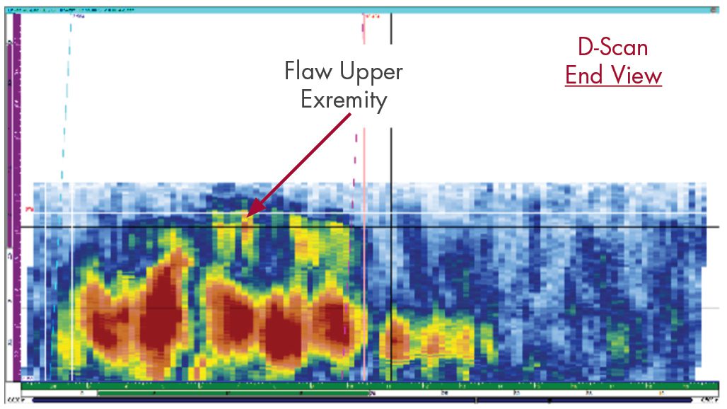
NUREG-1509 includes an evaluation of a postulated flaw in structural steel members, in accordance with the fracture toughness approach in ASME Code, Section XI, Appendix G.  For Monticello, the bioshield is constructed of ASME A36 steel, which was considered for computation of the NDT temperature, resulting in an allowable fracture toughness based on the ASME code. However, when considering industry literature and prior SLR evaluations, this value was conservatively reduced for the Monticello Evaluation. The fracture mechanics evaluation from NUREG-1509 was reproduced, using inputs from the steel liner FEA and bioshield heat transfer analysis.  The resulting analysis demonstrated sufficient margin between the applied stress intensity and conservative allowable fracture toughness, confirming that the Monticello bioshield would remain intact with no potential for brittle fracture even in the event of a postulated flaw.

Figure 6. Simplified heat transfer model for bioshield.

Conclusions
SI completed a first-of-a-kind evaluation of the Monticello bioshield, assessing long-term adequacy of the structural steel and concrete with exposure to irradiation and thermal effects.  The analysis introduced reasonable inputs in place of overly conservative assumptions and considered multiple potential aging mechanisms in order to comprehensively assess future conditions.  The results of the evaluation were accepted by the NRC, demonstrating a success path to perform similar evaluations for other sites pursuing LR/SLR.  These analyses are unique on a case-by-case basis, as each plant’s design, construction, and operational history will result in different regions and/or components being included in the evaluation.


References

  1. U.S. NRC Report NUREG-2192, “Standard Review Plan for Review of Subsequent License Renewal Applications for Nuclear Power Plants,” July 2017.
  2. U.S. NRC Report NUREG-1509, “Radiation Effects on Reactor Pressure Vessel Supports,” May 1996.


Get News & Views, Volume 54

News and Views, Volume 55 | UPDATE: Encoded Phased Array Ultrasonic Examination Services for Cast Austenitic Stainless Steel (CASS) Piping Welds in Pressurized Water Reactor (PWR) Coolant Systems

By:  John Hayden and Jason Van Velsor

Our initial article on this topic in News & Views, Volume 531 describes the challenges imposed by cast austenitic stainless steel (CASS) materials and the development of our CASS UT Examination solution. At the time of the prior article’s publication, SI was also conducting examinations of numerous CASS piping specimens. This article provides details of both that performance demonstration and the results of those examinations.

TYPICAL CASS PIPING WELD LOCATIONS IN PWR REACTOR COOLANT SYSTEMS
Figure 1 illustrates the presence of CASS piping components, both statically and centrifugally cast, in the primary Reactor Coolant Systems of many U.S. PWR plants. Other PWR plant designs also contain CASS components, albeit in fewer locations and only in the form of short spool piece segments, usually for reactor coolant pumps and safety injection system safe ends.

Figure 1. Locations of CASS piping components, both statically and centrifugally cast, in primary Reactor Coolant Systems of many U.S. PWR plants

REGULATORY BASIS FOR CASS EXAMINATION CAPABILITY
ASME Section XI Code Case N-824, which was approved by the NRC in 2019, provides specific direction and requirements for ultrasonic examination of welds joining CASS components. N-824 was incorporated into Section, XI, Appendix II, Supplement 2 in the 2015 Code edition. The NRC has stated (10CFR50.55a, 07/18/2017) that with use of the aforementioned N-824 methodology “Licensees will be able to take full credit for completion of the § 50.55a required in-service volumetric inspection of welds involving CASS components.” SI’s procedure development and demonstration were therefore based on these requirements.

ULTRASONIC TECHNIQUE PERFORMANCE DEMONSTRATION
Though not required by the ASME Code, SI conducted a performance demonstration of our CASS UT system at our facility in Huntersville, NC. Using CASS piping system specimens on loan from the EPRI NDE Center, SI successfully validated our ultrasonic examination system capabilities as follows.

Ultrasonic Procedure – SI’s CASS ultrasonic examination procedure is fully compliant with ASME Section XI Code documents, and NRC-imposed technical approval conditions. The procedure has also been optimized with many insights gained from our laboratory experiences while examining EPRI-owned CASS piping specimens.

Ultrasonic Equipment – The ultrasonic system components required by Code have been designed and fabricated by SI or purchased, including the following:

  • Ultrasonic instrumentation capable of functioning over the entire prescribed ranges of examination frequencies. The standard examination frequency range extends from low-frequency, 500 KHz operation for CASS pipe welds > 1.6” Tnom and 1.0 MHz for CASS pipe welds ≤ 1.6” Tnom
  • Transducer arrays were employed to meet the physical requirements of frequency and aperture size capable of generating the Code-prescribed wave mode, examination angles, and focal properties.
  • An assortment of wedge assemblies were designed and fabricated then mated with transducer arrays to provide effective sound field coupling to the CASS components being examined.

Data encoding options necessary to acquire ultrasonic data given the expected range of component access and surface conditions are available. The encoding options include:

  • A fully-automated scanning system capable of driving the relatively large and heavy 500KHz phased array probes. This system was used during our laboratory examinations of CASS piping specimens.
  • A manually driven encoding system — a proven, field-worthy tool — which may be employed in locations where fully automated systems cannot be used because of access restrictions.

Examination Personnel – The challenges that exist with the examination of CASS piping welds warrant a comprehensive program of specialized, mandatory training for personnel involved with CASS examinations. This training includes descriptions of coarse grain structures, their effect on the ultrasonic field, the expected ultrasonic response characteristics of metallurgical and flaw reflectors, and the evaluation of CASS component surface conditions.

Additionally, SI’s ultrasonic examination personnel are thoroughly trained and experienced in all elements of encoded phased array ultrasonic data acquisition and analysis in nuclear plants and hold multiple PDI qualifications in both manual and encoded phased array DM weld techniques.

EPRI CASS PIPING SPECIMENS
The EPRI CASS pipe specimens, their outside diameter (OD) and thickness dimensions, and butt weld configurations examined by SI are described below.

12.75″ OD, 1.35″ Tnom SPECIMENS
Three pipe-to-pipe specimens representative of piping found in pressurizer surge and safety injection applications were examined. Each of these specimens had the weld crown ground flush.

Figure 2. Schematic of 12.75” OD, 1.35” Tnom CASS specimens.

Figure 3, Figure 4, and Figure 5 present examples of ultrasonic data images of a flaw detected in a 12.75” OD pipe-to-pipe tapered specimen.

Figure 3. Representative ultrasonic C-Scan data image from 12.75” OD, 1.35” Tnom specimen.

The C-Scan is a 2-D view of ultrasonic data displayed as a top (or plan) view of the specimen. The horizontal axis is along the pipe circumference, and the vertical axis is along the pipe axis or length.

Figure 4. Representative ultrasonic B-Scan data image from 12.75” OD, 1.35” Tnom specimen.

The B-Scan is a 2-D view of ultrasonic data displayed as a side view of the specimen. The angular projection of the data is displayed along the examination angle. The horizontal axis is along the pipe axis, and the vertical axis is along the pipe thickness.

Figure 5. Representative ultrasonic D-Scan data image from 12.75” OD, 1.35” Tnom specimen.

The D-Scan is a 2-D view of ultrasonic data displayed as an end view of the specimen. The horizontal axis represents the pipe circumference, and the vertical axis is along the pipe thickness.

28″ OD, 2.0″ Tnom SPECIMENS
Four pipe-to-pipe specimens representative of piping found in reactor coolant loops were examined. Each of these specimens had the weld crown intact and left in place.

Figure 6. Schematic of 28” OD, 2.0” Tnom CASS specimens.

Figure 7, Figure 8, and Figure 9 present examples of ultrasonic data images of a flaw detected in a 28” OD pipe-to-pipe tapered specimen.

Figure 7. Representative ultrasonic C-Scan data image from 28” OD, 2.0” Tnom specimen.

The C-Scan is a 2-D view of ultrasonic data displayed as a top (or plan) view of the specimen. The horizontal axis is along the pipe circumference, and the vertical axis is along the pipe axis or length.

Note the ability of our UT data acquisition equipment and data analysis techniques to resolve, discriminate, and identify inside surface geometric conditions (weld root and pipe counterbore), along with detecting and sizing the flaw indication. Also, note the excellent signal-to-noise ratio achieved.

Figure 8. Representative ultrasonic B-Scan data image from 28” OD, 2.0” Tnom specimen.

The B-Scan is a 2-D view of ultrasonic data displayed as a side view of the specimen. The angular projection of the data is displayed along the examination angle. The horizontal axis is along the pipe axis or length. The vertical axis is along the pipe thickness.

Figure 9. Representative ultrasonic D-Scan data image from 28” OD, 2.0” Tnom specimen.

The D-Scan is a 2-D view of ultrasonic data displayed as an end view of the specimen. The horizontal axis is along the pipe circumference, and the vertical axis is along the pipe thickness.

28″ to 29″ OD, 2.0″ to 2.5″ Tnom TAPERED WELD SPECIMENS
Four pipe-to-pipe specimens, with tapered weld surfaces representative of piping found in reactor coolant loops were examined.

Figure 10. Schematic of 28” to 29” OD, 2.0” to 2.5” Tnom CASS specimens.

Figures 11, 12, and 13 present examples of ultrasonic data images of a flaw detected in a 28” OD to 29” OD pipe-to-pipe tapered specimen.

Figure 11. Representative ultrasonic C-Scan of a 28” to 29” OD, 2.0” to 2.5” Tnom pipe-to-pipe, with tapered weld surfaces.

The C-Scan is a 2-D view of ultrasonic data displayed as a top (or plan) view of the specimen. The horizontal axis is along the pipe circumference, and the vertical axis is along the pipe axis, or length.

Figure 12. Representative ultrasonic B-Scan of a 28” to 29” OD, 2.0” to 2.5” Tnom pipe-to-pipe, with tapered weld surfaces.

The B-Scan is a 2-D view of ultrasonic data displayed as a side view of the specimen. The angular projection of the data is displayed along the examination angle. The horizontal axis is along the pipe axis or length. The vertical axis is along the pipe thickness.

Figure 13. Representative ultrasonic D-Scan of a 28” to 29” OD, 2.0” to 2.5” Tnom pipe-to-pipe, with tapered weld surfaces.

The D-Scan is a 2-D view of ultrasonic data displayed as an end view of the specimen. The horizontal axis is along the pipe circumference, and the vertical axis is along the pipe thickness.

SUMMARY OF DATA ANALYSIS RESULTS
Documentation was provided for each EPRI specimen, which contains flaw location, length, and through-wall size to permit the comparison of UT data acquisition and analysis processes to actual flaw conditions.

All of the 23 circumferential flaws in the eleven EPRI specimens were detected. The ultrasonic examination and data analysis techniques achieved flaw location and length sizing RMS errors, which are within acceptance standards of the following ASME Section XI, Appendix VIII Qualification Supplements:

  • Supplement 2, Qualification Requirements for Wrought Austenitic Stainless Steel Piping
  • Supplement 10, Qualification Requirements for Dissimilar Metal Piping

Excellent signal-to-noise ratios were observed for all detected flaws.

For all flaws, the measured length achieved sizing RMS errors within the acceptance standards of the above Appendix VIII supplements.

For specimens with welds ground flush and for all specimens with sufficient access to interrogate the entire through-wall extent of flaws, SI’s technique achieved through-wall sizing RMS errors within the acceptance standards of the above Appendix VIII supplements.

To be clear, the examination of the EPRI CASS specimens does not meet the rigor of Appendix VIII, Supplement 9 qualification because the industry’s (PDI Program) for CASS piping welds is still in preparation. The comparison to Appendix VIII acceptance standards is provided solely as a means to describe the achieved flaw detection and sizing capabilities in CASS material in terms of already established PDI qualifications. Ongoing examination of additional CASS specimens will strengthen already existing ultrasonic examination capabilities and experience.

CONCLUSIONS
The CASS piping welds in many PWR plants provide numerous and complicated challenges to their effective ultrasonic examinations. Most, if not all, CASS RCS piping welds have not been subjected to a meaningful and effective volumetric examination since radiography was conducted during plant construction.  SI’s newly-demonstrated ultrasonic examination procedure for CASS delivers a demonstrated, Code-compliant, meaningful, and effective solution that provides full credit for completion of in-service volumetric inspection per § 50.55a.

References

  1. News and Views, Volume 53, October 2023, “Encoded Phased Array Ultrasonic Examination Services for CASS Piping Welds In PWR Reactor Coolant Systems”
  2. ASME Section XI Code Case N-824, “Ultrasonic Examination of Cast Austenitic Piping Welds from the Outside Surface”
  3. ASME B&PV Code, Section XI, 2015 Edition and later editions

Download PDF