News and Views, Volume 54 | Leaks in High Energy Piping Tees
By Kane Riggenbach and Eric Jones
Background
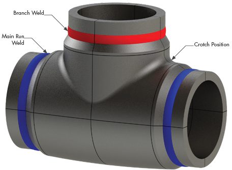
Figure 1. Representative HEP Tee Geometry
The power generation industry has seen an increasing trend of failures and damage detected in high energy piping tee fittings and the associated girth welds in systems made from grade 91 material (and grades 22 and 92). Failures and evidence of significant creep damage have been detected in less than 100,000 operating hours in many cases and as few as 35,000 operating hours. The issues stem from inadequate reinforcement of the branch leg and/or short tee leg lengths, which can result in tee geometries not suitable for high temperature service even though the tee fittings meet design requirements. If inspections reveal that damage has progressed beyond the point where continued operation can be justified through analytical methods with appropriate confidence and risk tolerance, owners may be faced with a choice of expensive temporary repair or long wait for a replacement. The lead time to procure replacements can be twelve months or greater and additional rigorous engineering assessments to determine size specifications may be required because current code requirements are inadequate in some cases.
Issue Overview
Many fabricated tees have failed to withstand short-term exposure to normal operating pressures and temperatures. Analytical assessments have determined that these premature failures can be attributed to a lack of sufficient reinforcement, despite the components in question meeting code design requirements. Additionally, large variations in thickness and diameter and differences in crotch profiles can exist even among similarly sized tee fittings, resulting in uncertainty when trying to extrapolate findings between tees in a system, plant, or fleet. These challenges make it difficult for plant owners to prioritize specific tees for inspection. Experience has shown that there can be significant differences in tee thickness/geometry even among tees produced by the same manufacturer or from one tee crotch to the other. As such, baseline inspections are recommended on all tees operating in the creep regime to comprehensively document their serviceability risk and develop an informed lifecycle management plan.
The applied inspection approach is also adjusted to ensure accurate and reliable detection of damage.
Traditionally, welds have been the most susceptible locations to creep damage in high energy piping systems, so most inspections were solely focused there. For fabricated tee fittings, creep damage has also been detected in the fitting base metal within the crotch region. Localization of creep damage at the crotch region has been validated through finite element analysis based on actual tee geometry. Thus, inspections that were solely focused on girth welds may fail to identify or characterize damage in the tee crotches, providing an incomplete picture of overall condition even for recent inspections.
Damage Initiation
The primary driver of damage in tee geometry is from accumulated creep damage resulting from internal pressure stress. The hole in the pipe for the branch leg of the tee leads to elevated stresses that tend to drive axially oriented cracking in the tee crotch. Also, if the attached piping girth welds are close enough to this elevated stress region, these girth welds are at risk for faster rates of creep damage. As opposed to the axially oriented cracking in the tee base material, girth welds tend to initiate circumferentially oriented cracking due to the orientation of the creep weak weld heat-affected zone (HAZ).
Stresses from piping deadweight and thermal expansion may play a role in biasing damage towards a certain location. However, finite element analyses, ultrasonic inspections of in-service tees, and metallurgical evaluations of cross-sections from ex-service tees have all validated that the distribution of creep damage is consistent with the stress distribution from internal pressure stresses. Figure 2 shows two example ultrasonic phased array scans (left) depicting subsurface indications that are consistent with the creep redistributed FEA stress distribution (right).
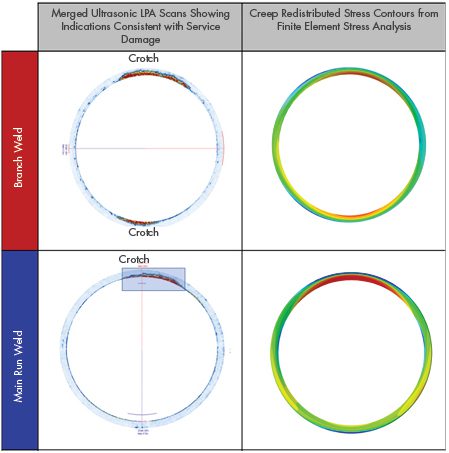
Figure 2. Examples of Phased Array Ultrasonic Scans with Indications and Finite Element Color Contour Stress Distribution.
Inspection Considerations
SI has performed numerous inspections of tee fittings and associated girth welds. From those efforts, a series of lessons learned and recommended best practices have been developed:
- For girth welds, damage can be OD or ID initiated depending on the local geometry and stress state of the component. Damage tends to initiate at the circumferential positions closest to the tee crotches so extra priority should be given toward assessing these areas. The tee side of the weld may include an OD bevel that obstructs UT probe placement on the tee side, but attempts should still be made to scan from both upstream and downstream sides of the weld.
- For crotch regions, identified damage tends to be ID or subsurface initiated. Additional surface preparation is required in the crotch to permit ultrasonic scanning. Specialized inspection hardware may be necessary to accurately identify and characterize damage because the complex curvature of the OD crotch surface can limit probe contact area (probe bridging) and the thickness of the tee may make it difficult to observe the ID surface. Specially radiused probes or refracted longitudinal probes may be necessary to enable more accurate scanning of the crotch.
- Extensive thickness mapping is recommended to fully document the as-built geometry of the tee and identify whether any ID stress concentrations may be present from manufacturing of the tee. An example tee grid is depicted in Figure 3.
- Laser scanning or photogrammetry should be performed to provide the basis for a representative external surface for detailed model creation and finite element analysis on all inspected tees as well as to ensure that the exact location of recorded thicknesses is documented. This scan or set of photographs also provides the basis for a representative external surface for detailed model creation and finite element analysis.
- There are multiple documented cases where tees progressed from “No Indications of Service Damage Detected” to macrocracking in far less time than a normally reasonable reinspection interval for girth welds. For this reason, as well as the likelihood that many inspections have been performed without evaluating the tee crotch areas, previously established reinspection intervals may be unreliable, and it is critical for operators with these components to perform an analytical assessment and adjust inspection plans accordingly.
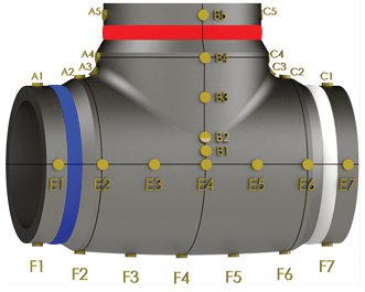
Figure 3. Example of general grid for thickness documentation. Additional thickness mapping should be performed at the crotch regions as well.
Industry Response / EPRI Supplemental Project
The operational challenges associated with premature degradation of high energy piping tees have led to significant industry interest in understanding the factors which combine to result in accelerated damage. The Electric Power Research Institute (EPRI) has initiated a supplemental project focused on studying this issue for tees operating in the creep regime. The project members are comprised of numerous utilities along with service providers (including SI), with a goal of summarizing operating experience and establishing reputable guidance for operators.
One of the early observations from the project is that the quality and consistency of inspection data is critical to problem characterization. There have been multiple instances where lack of pre-planning, inadequate surface preparation, and/or failure to compile adequate data and records have challenged the integrity of inspections. To help improve characterization and increase the accuracy of predictive models, SI is working to standardize NDE inspection techniques utilizing a number of components removed from service.
Recommendations for Utilities/Operators
Based on SI’s experience with tees operating in the creep regime, it is recommended that operators consider the following guidance:
- Perform inspection to document the actual fabricated tee geometry, assess material composition, and determine current condition of the tee and associated girth welds. Ensure that the inspection provider can deliver complete and accurate results in a fashion that informs decision making.
- Estimate the creep life in accordance with an appropriate analytical assessment method using actual measured tee geometry and operating data. This step necessitates appropriate material correlations for creep strain rate to determine creep redistributed stresses and appropriate creep rupture correlations for calculations to predict time to crack initiation.
- If appropriate based on life estimation results, schedule subsequent condition assessments to look for damage at an appropriate point with respect to estimated damage accumulation and risk tolerance.
- Consider reviewing and pre-planning mitigation options prior to scheduling inspections.
-
- Planning should account for the fact that fitness for service assessments may not result in extensive times to through-wall crack propagation. Stresses in the crotch region have been fairly uniform resulting in short remaining life projections.
- Planning needs to account for the fact that potentially inadequate tee design requirements are still being addressed by the code committees, and, as such, off-the-shelf replacement tees may also lack reinforcement to ensure appropriate service lifetimes.


