News & Views, Volume 53 | Phased Array Ultrasonic Testing (PAUT) Monitoring with Ultrasonic Thick-Film Arrays
Traditional nondestructive examination (NDE) activities are planned based on hours of service, number of load cycles, time elapsed since previous inspections, or after the emergence of clear and obvious damage in a component. While engineering judgment and risk analysis can, and should, be used to prioritize inspections, these prioritizations are not based on the actual physical condition of the component or material it is constructed from but on precursory conditions that may or may not lead to eventual damage. Alternatively, continuous monitoring approaches can facilitate advanced planning and the optimization of Operations and Maintenance (O&M) spending by enabling the prioritization of inspections based on a component’s actual current condition. Furthermore, continuous monitoring enables earlier detection, which allows the extension of the component’s remaining useful life through modified operation.
SI’s recent advances with thick-film are breakthrough technologies for long-term monitoring and imaging of crack growth in critical components.
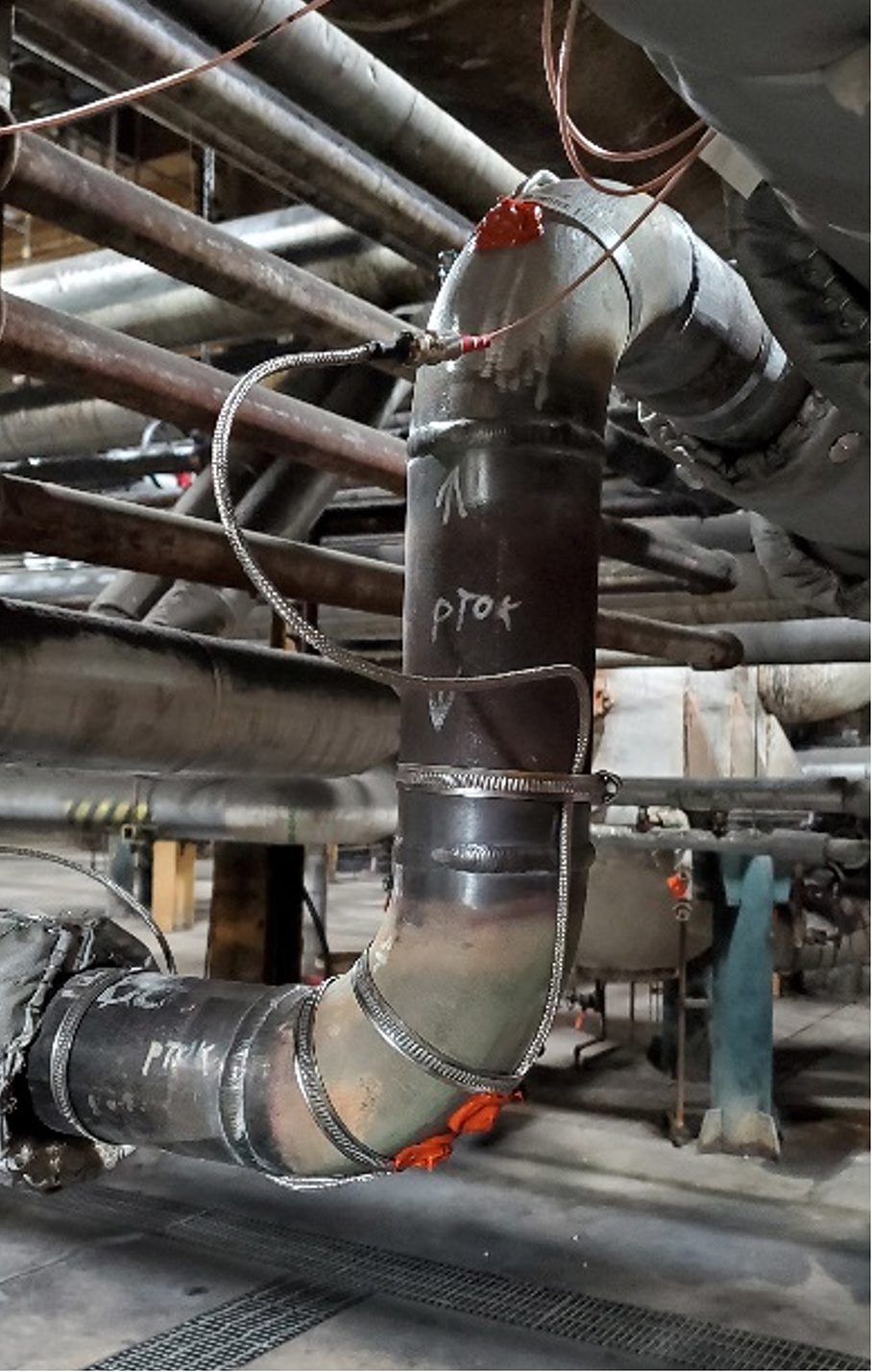
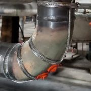
Figure 1. Installed thick-film UT sensors for thickness monitoring of elbows.
Given the trend of fewer on-site resources and tighter O&M budgets, the energy industry has a strong motivation to progress toward condition-based inspection and maintenance. To facilitate this evolution in asset management strategy, new monitoring sensor technologies are needed, ones that provide meaningful monitoring data directly correlated to the condition of the material or asset. To support this need Structural Integrity has developed a novel thick-film ultrasonic sensor solution. Initially developed for basic applications, such as thickness monitoring, SI’s recent advances with this technology make long-term monitoring and imaging of crack growth in critical components possible.
BACKGROUND
Ultrasonic thick-films are comprised of a piezoelectric ceramic coating that is deposited on the surface of the component that will be monitored. A conductive layer is then placed over the ceramic layer, and the ceramic layer deforms when an electric potential is applied across the film. When a sinusoidal excitation pulse in the ultrasonic frequency range is applied across the film, the vibration of the film is transferred into the test component as an ultrasonic stress wave.
Structural Integrity initially developed our thick-film ultrasonic sensors for real-time thickness monitoring and has demonstrated the performance and longevity of this technology through laboratory testing and installation in industrial power plant environments, as seen in the photograph in Figure 1, where the sensors have been installed on multiple high-temperature piping components that are susceptible to wall thinning from erosion. In this application, the sensors are fabricated directly on the pipe’s external surface, covered with a protective coating, and then covered with the original piping insulation. Following installation, data can either be collected and transferred automatically using an installed data acquisition instrument, or a connection panel can be installed that permits users to acquire data periodically using a traditional off-the-shelf ultrasonic instrument. Example ultrasonic datasets are shown in Figure 2.
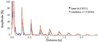
Figure 2. Ultrasonic datasets from an installed thick-film UT sensor at two different points in time.
TECHNOLOGY ADVANCEMENTS
Recently, SI has demonstrated the ability to create thick-film sensors with complex element arrays that can be individually controlled to steer and focus the sound field, as with traditional phased-array ultrasonic testing (PAUT). Moreover, data from individual array elements can be acquired and post-processed using full-matrix capture (FMC) techniques. FMC is a data acquisition technique where all elements in the array are used to both transmit and receive ultrasonic waves. The result is a large data matrix that can be used for further processing with various post-processing techniques. Compared to more traditional active focusing, FMC is well-suited for a fixed transducer array, as scanning speed is not a concern. Another advantage is that the electronics needed for data acquisition can be simplified – requiring only a single pulsing channel.
A thick-film Linear-Phased Array (LPA) installed on a standard calibration block is shown in Figure 3. The two images shown on the right were generated using the Total Focusing Method (TFM) post-processing algorithm, with the image on the far right having an adjusted color scale to highlight the imaging of the notches toward the bottom of the calibration block. TFM is an amplitude-based image reconstruction algorithm where the A-scans from the FMC dataset are used to synthetically focus on every point in a defined region of interest.
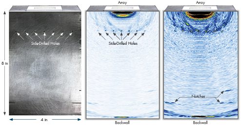
Figure 3. FMC TFM results from a thick-film linear phased array installed on a calibration block.
Using other information from the FMC dataset, such as the phase of the waveforms, has proven to be beneficial in certain cases. At each focal point in the region of interest, a large phase coherence among all the waveforms can be indicative of a focused reflector. This can then be applied to the TFM image at each focal point as a weighting factor (also known as the Phase Coherence Factor (PCF)) to improve the signal-to-noise ratio.
Figures 4 and 5 illustrate the results of applying the phase coherence imaging technique to the FMC datasets collected with thick film transducer arrays. The sample is a section of high-energy piping approximately 1.7 inches thick with cracking at various positions along a girth weld. The sample has a counterbore with ID-initiated cracks up to approximately 0.5 inches in length coming from the taper of the counterbore. The thick film transducer arrays were located at different positions along the weld.
SUMMARY
The energy industry is moving away from traditional scheduled-based planning for inspection and maintenance activities and toward “smart plant” concepts that rely more heavily on data correlated to actual component conditions. To accomplish this, there is a need for new and novel monitoring technologies that are both unobtrusive and able to withstand the harsh conditions of industrial facilities. Collecting robust and meaningful monitoring data will be critical in ensuring that safety and asset reliability are maintained and even improved. Structural Integrity’s thick-film UT technology has been developed to achieve this goal and continues to evolve for higher-temperature components and more advanced applications. We are ready to support a variety of in-field applications, contact one of SI’s experts if you have questions or a potential application that could benefit from installed thick-film UT sensors.

Figure 4. Phase coherence imaging result from a thick film transducer array on a cracked weld sample.
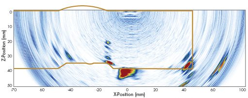
Figure 5. Phase coherence imaging result from a thick film transducer array on a cracked weld sample.

