SI Selected in The Corporate Magazine’s “Top 20 Most Dynamic Leaders”

To read the full article, click here.

To read the full article, click here.
A CASE STUDY FROM THE FERMILAB LONG BASELINE FACILITY
By: Keith Kubischta and Andy Coughlin, PE, SE
Background
In Batavia, Illinois a facility being built that is the first of its kind in the world. Fermilab’s Long Baseline Neutrino Facility will accelerate protons using electromagnets up to incredible speeds in a particle accelerator. After traveling through the campus, the particles are redirected to a graphite target where the collision breaks them into their component particles: pions and muons. These components decay and are segregated off. What is left is believed to be the building blocks of the universe: neutrinos, which can pass undisturbed through matter. A beam of neutrinos passes through near detectors and travels over 800 miles underground to a detection facility in an old mineshaft at Sanford Underground Research Facility in South Dakota, a facility that can also detect neutrinos hitting the earth from exploding stars.

Figure 1. Fermilab Long Baseline Neutrino Facility (source https://mod.fnal.gov/mod/stillphotos/2019/0000/19-0078-02.jpg)
After the graphite collision what is left behind has the potential to create some harmful biproducts such as tritium, or hydrogen-3, which needs to be kept out of the surrounding atmosphere, soil, and ground water. This occurs in the decay region slightly downstream from the target complex, which is 630-ft long concrete tunnel with 18 feet of concrete surrounding the beam line. Exiting the decay tunnel any leftover particles are absorbed downstream in the absorber hall.

Figure 2. Overview of Decay Region
The tunnel of the decay region houses an octagonal shielding concrete structure to provide shielding for the byproducts. This octagonal structure is over fifty feet tall and wide with 42,000 cubic yards of concrete, enough concrete to construct a baseball stadium. At the center of the tunnel is a double walled stainless steel pressure vessel charged with helium on the inside and a chilled flow of nitrogen gas within the annulus. The octagonal shielding concrete structure is surrounded by an access area to inspect the structure, the outer decay tunnel walls, and the surrounding soil.
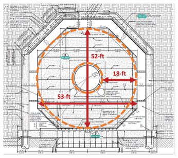
Figure 3. Typical Decay Region Tunnel Cross Section
The octagonal shape of the shielding concrete was not always so octagonal. Starting off with small steps, Structural Integrity demonstrated advanced capabilities to model thermal structural behavior of mass concrete, while developing and expanding on existing capabilities. SI’s positive impact on the early stages of the project earned us a larger role where we displayed additional capabilities to positively influence the design of the structure.
SI followed the design progression and answered some critical questions, such as:
SI answered these questions and more through expert analysis, expanding our capabilities through proprietary simulation ranging from earlier design concepts, construction stages, and up to including a 50-year design life of the structure.
Part One of this article will look at the influence our work had of the design of the massive structure and the benefits of “seeing the cracks” before they happen.
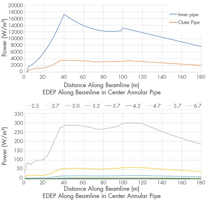
Figure 4. EDEP Axial and Radial Distribution along the Beamline
Energy Deposition and Cooling Thermodynamics
Concrete that gets too hot can vaporize the pore water and even break apart. The transfer of heat in concrete is a critical component of the analysis and is both added to the structure and removed. Thermal loading was provided by Fermilab in the form of volumetric energy deposition (EDEP) on the concrete and steel based on particle physics software simulation program MARS. The distribution of EDEP varies both radial outward from the beamline and compounded by its positioning along the length of the tunnel. SI would need to convert the distribution into a subroutine of distributed flux for use by the analysis program. The distribution was first translated for use in 2D analysis, expanded into 3D space, and then rotated in coordinate space to account for the slope of the beamline. With the EDEP adding heat to the system, chilled nitrogen is needed to remove heat.
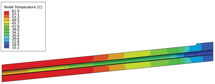
Figure 5. Accurate Thermal Distribution along the Decay Tunnel Shielding Concrete Structure.
A bit of “back-to-school” was needed to solve the thermodynamic problem. The heat transfer coefficient and temperatures of the nitrogen gas cooling system were calculated using classical methods on convection relationships in annular spaces. With the known EDEP into the concrete and steel, which dominates in regions closer to the center, it was decided as a design condition that all heat be taken by the nitrogen to obtain the outflow temperature of the nitrogen gas. The nitrogen temperature was calculated in 10m increments along the annular pressure vessel and at outflow based on an energy balance equation. The heat transfer coefficient was calculated using three different empirical relationships for Nusselt number utilizing the lower bound conservative estimate in the analysis. Our efforts created an accurate model in 3D space of the heat transfer into the shielding concrete. As a result of the nitrogen cooling system, we were able to keep concrete temperatures below the limit of 110 degrees Celsius. With the thermodynamic problem solved, SI progressed, coupling the solution to the mechanical stress model.
Concrete Capabilities
If there is one thing concrete is guaranteed to do, it is to crack. SI’s proprietary concrete constitutive model, ANACAP, is designed to predict concrete cracking and preform under various states of those cracks opening and closing. The behavior of concrete is highly nonlinear with low tensile strength, shear stiffness and strength that depend on crack widths, and plasticity compression. The main components of the concrete model utilized in the design phase analyses are tensile cracking, post-cracking shear performance, and compressive yielding when the compressive strength is reached. The use of the ANACAP concrete model has been validated and verified through 30 years of use and a key component for the nonlinear assessments.
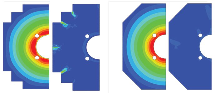
Figure 6. Stepped vs Octagonal Cross Section, Thermal Distributions and Concrete Strain (Cracking)
Influence on Design
Accurate modeling of thermodynamics / thermal analysis, coupling with the mechanical model / stress analysis, and the capabilities of the nonlinear constitutive concrete model allow for the simulation of a full 3D model of the shielding concrete under full power operations. The design team sought to minimize the cracking of the structure, monitor elongations and other movements affecting the beam line, and design connections at the structure boundaries. SI coordinated with research and design teams to facilitate several cross-section iterations with different shapes and layers of shielding. Each design iteration was analyzed to demonstrate the benefits or consequences. An early iteration of the shield concrete cross-section was a stepped block shape. The corners of the stepped cross-section displayed the potential for cracking. SI addressed this potential design trait through influencing the development of the octagonal section shape. This optimization allows the design to minimize the amount of reinforcement needed to control cracking.
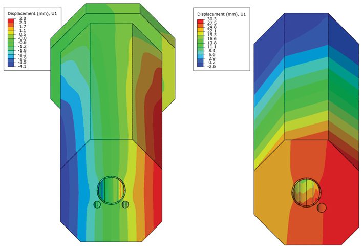
Figure 7. Lateral Displacements of Single Return Pipe and Dual Return Pipe
In addition to the cooling annulus at the center of the structure, there are the return ducts for the system to bring the nitrogen back to the target complex facility. The design initially used four return pipes spread out at four different corners. In one iteration the design team attempted to reduce the four return ducts to one larger return pipe to reduce the concrete volume required for shielding. The design iteration with one return duct was attempting to reduce costs by reducing the overall amount of concrete needed. Our calculations quickly identified unintended consequences. The asymmetrical shape was creating displacements along the transverse horizontal direction, pushing the beam alignment off-center by over an inch (~30 mm). The shape was quickly updated to be symmetric with two return pipes.
From room temperature to 60 degrees Celsius, concrete is going to expand. Traditional thermal breaks cannot be utilized in this structure to maintain continuity and provide shielding. The design needed to allow the structure to expand at the downstream end. Most of the structure is supported by rails where it was designed to freely slide at the bottom of the octagonal section during the expansion phase. A section of these rails needs to be fixed at the upstream end where it was designed to resist the gravity of the structure along the slope. SI provided valuable design influence with where the fixed rails were to be positioned as the thermal loading created immense stress at the location between the fixed boundary and sliding boundary. In the original position, SI’s calculations identified a concentrated area of cracking. To minimize the amount of cracking and additional reinforcement needed, SI proposed moving the position of restraint towards the cool / upstream end of the tunnel.
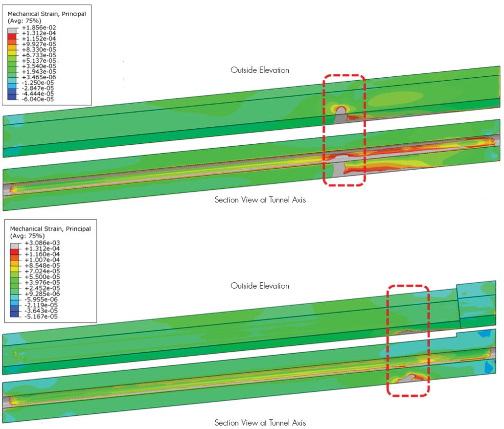
Figure 8. Effect of Fixed Rail Boundary Condition Position on Strain.
How do you stop 42,000 cubic yards of concrete from expanding?
Answer: You Don’t.
Conclusions
Structural Integrity successfully developed expanded capabilities to model thermodynamics for the energy deposition and nitrogen cooling system. SI used the capabilities of our concrete model to influence the structural design by “seeing the cracks” before they happen, making design adjustments, and reducing reliance on additional reinforcement. SI was able to give key insights for the concrete structure and potential cost savings through optimization.
Part Two of this article will look at the life of the structure form the day concrete is first poured to 30 years of power cycles. Delving into the future to see this structures test of time and monitoring methods to see if our predictions come true.
TECHNOLOGY INNOVATION – THICK FILM SENSORS
By: Jason Van Velsor and Robert Chambers

Figure 1 – Photograph of an ultrasonic thick-film array for monitoring wall-thickness over a critical area of a component.
Over the last several years, Structural Integrity has been working on the development of a real-time thickness monitoring technology that utilizes robust, unobtrusive, ultrasonic thick-film sensor technology that is enabling continuous operation at temperatures up to 800°F. Figure 1 shows a photograph of an installed ultrasonic thick-film array, illustrating the low-profile, surface-conforming nature of the sensor technology. The current version of this sensor technology has been demonstrated to operate continuously for over two years at temperatures up to 800°F, as seen in the plot in Figure 2. These sensors are now offered as part of SI’s SIIQ™ intelligent monitoring system.
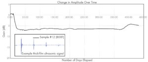
Figure 2 – A plot of ultrasonic signal amplitude over time for a sensor operating continuously at an atmospheric and component temperature of 800°F.
In addition to significant laboratory testing, the installation, performance, and longevity of Structural Integrity’s thick-film ultrasonic sensor technology has been demonstrated in actual operating power plant conditions, as seen in the photograph in Figure 3, where the sensors have been installed on multiple high-temperature piping components that are susceptible to wall thinning from erosion. In this application, the sensors are fabricated directly on the external surface of the pipe, covered with a protective coating, and then covered with the original piping insulation. Following installation, data can either be collected and transferred automatically using an installed data acquisition instrument, or a connection panel can be installed that permits users to periodically acquire data using a traditional off-the-shelf ultrasonic instrument.
Figure 4 shows two sets of ultrasonic data that were acquired approximately eight months apart at an operating power plant. The first data set was acquired at the time of sensor installation and the second data set was acquired after approximately eight months of typical cycling, with temperatures reaching up to ~500°F. Based on the observed change in the time-of-flight between the multiple backwall echoes observed in the signals, it is possible to determine that there has been approximately 0.005 inches of wall loss over the 8-month period. Accurately quantifying such as small loss in wall thickness can often provide meaningful insight into plant operations and processes, can provide an early indication of possible issues, and is only possible when using installed sensors.
Other potential applications of Structural Integrity’s ultrasonic thick-film sensor technology include the following:
In addition to novel sensor technologies to generate data, Structural Integrity offers customizable asset integrity management solutions, as part of the SIIQ platform, such as PlantTrackª, for storing and managing critical data. Many of these solutions are able to connect with plant historians to gather additional data that feed our engineering-based analytical algorithms, which assist in converting data into actionable information regarding plant assets. These algorithms are based on decades of engineering consulting and assessment experience in the power generation industry.
Reach out to one of our NDE experts to learn more about SI’s cutting-edge thick-film UT technology.
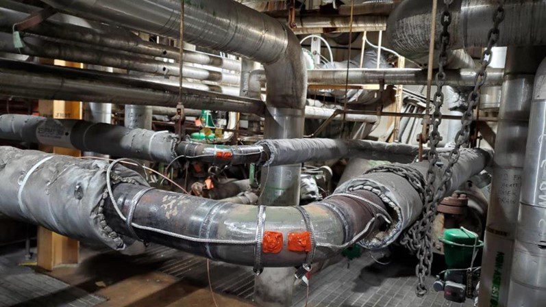
Figure 3 – Photograph showing Structural Integrity’s thick-film ultrasonic sensor technology installed on two high-temperature piping elbows that are susceptible to thinning from erosion.
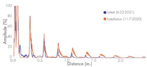
Figure 4 – Ultrasonic waveforms acquired approximately 8 months apart showing 0.005 inches of wall loss at the sensor location over this period.
ENGINEERING CRITICAL ASSESSMENT
By: Pete Riccardella, Scott Riccardella and Chris Tipple
The Structural Integrity Associates, Inc. Oil and Gas Pipeline group recently supported an Engineering Critical Assessment to assist a pipeline operator manage the Selective Seam Weld Corrosion (SSWC) threat to an operating pipeline. SSWC occurs when the fusion zone of a certain type of seam weld used in vintage (pre-1970) transmission pipelines experiences accelerated galvanic corrosion relative to the pipe body material. It has led to numerous pipeline failures because the weld fusion zone often exhibits low fracture toughness. The ECA included several technical advancements in applying fracture mechanics to this threat.
By: Wenfeng Liu
Introduction
PEGASUS, a finite element fuel code developed at SIA, represents a new modeling paradigm. This new paradigm treats all fuel behavior regimes in one continuous analysis. This approach differs significantly from the current conservative practice of bounding analysis to ensure uncertainties are accounted for which results in sub-optimal used fuel management strategies. Using PEGASUS in used fuel evaluation results in significant savings in engineering cost and work force utilization, reduces conservatism, and provides flexibility in the management of used fuel.
SOFTWARE AUTOMATION
By: Adam Roukema and Mark Jaeger
From Tech Pro Research, %’s reflect rate of respondents who believe digital transformation will significantly impact indicated categories
A fundamental tenant of engineering is that where inefficiencies exist, innovation is next. This is especially true in the ongoing era of digital transformation, as software-based automation eliminates mundane, trivial tasks and enables increased focus on value-add activities. A recent poll of workers in the tech industry found that 70% of their respective companies have either committed to or are developing a transformation strategy, with varying emphases (see sidebar). The energy sector is no stranger to these innovations, and while the pace and scope of digital transformation may not appear to match that of driverless cars or moon rockets, its societal impacts are comparably widespread.
Historically, SI has been recognized as a leader in highly technical subject matter areas such as fracture mechanics, material degradation, and nondestructive examination. In many cases, this expertise is aided by digital or software innovations that enable efficient data handling, novel computer aided visualizations, and dynamic performance of complex calculations. In this vein, our MAPPro software is designed to aid in management of aging piping assets and has been an integral resource to the nuclear industry since its inception in 2009.
EFFECTIVE ASSESSMENT TECHNIQUES
By: Matt David, Michael Greveling, Daniels Peters and Erick Ritter
Recently, Structural Integrity Associates (SI) helped a client with a leaking deaerator tank (DA tank). DA tanks are traditionally used to remove dissolved gasses from liquids. The client’s DA tank in particular is used to remove dissolved oxygen in feedwater for steam-generating boilers; this is done because dissolved oxygen can create a corrosive environment within the boiler as it will attach to the metal components, creating oxides. The DA tank protects the boiler from these corrosive gasses, however, to the DA tank’s detriment, not much protects it from those same gasses. Repairs on DA tanks are common and additionally it is not uncommon for those repairs to continue to experience problems.
The DA tank being investigated for leaking in this investigation had an entire shell segment, various full thickness patch plates, and a head replaced in 2018 due to wall thinning caused by flow-accelerated corrosion (FAC). The current leak was caused by cracking of a girth and longitudinal seam weld in a mismatched repair patch. The failure prompted inspection, stress analysis, and repair consulting by SI. The following reveals the steps taken to repair the failed DA tank.
Initial visual inspection of the leaking DA tank indicated that the problematic repair patch had significant radial mismatch relative to the tank shell to which it was welded and grossly oversized weld layers resulting in high tensile shrinking stresses. The mismatch resulted in significant bending at the weld line and the excessive weaving of the weld layers led to tensile forces acting on the weld imperfections at the toe of the welds. Due to the visual finding, 3D scanning was performed to better understand the magnitude of the mismatch.
COMPONENT LONGEVITY
By: John Molloy
Introduction
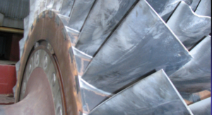
Figure 1. Compressor rotor inlet with fouling deposits
An industrial combustion turbine can ingest over 1000lbs of air per hour of operation. Entrained within the air is a spectrum of mineral, salt, moisture, and VOC, and other compounds that are present in the local atmosphere. Locally high concentrations of potentially corrosive species may also be present due to surrounding industries or even effluent from the power plant itself, such as cooling tower drift, evaporation cooler deposits, or water treatment effluent.
In addition to disrupting the flow path area of the compressor blades and vanes, with a consequential drop in compressor efficiency, these contaminants can also serve as sites for under-deposit corrosion cells that have implications for component life as well as risk for catastrophic failures. Compressor waterwashing with detergents has been utilized with some success by utilities as a method for mitigating the effects of deposit accumulation. Nevertheless, tenacious deposits can accumulate over time. The presence of moisture in the deposit can also result in activation of a corrosion cell that can corrode the typical stainless steels used for blade and vane construction. Higher strength PH stainless steel blades and vanes suffer a larger loss in fatigue endurance limit from pitting, and tend to suffer more airfoil liberations due to cracking initiated at pitting.
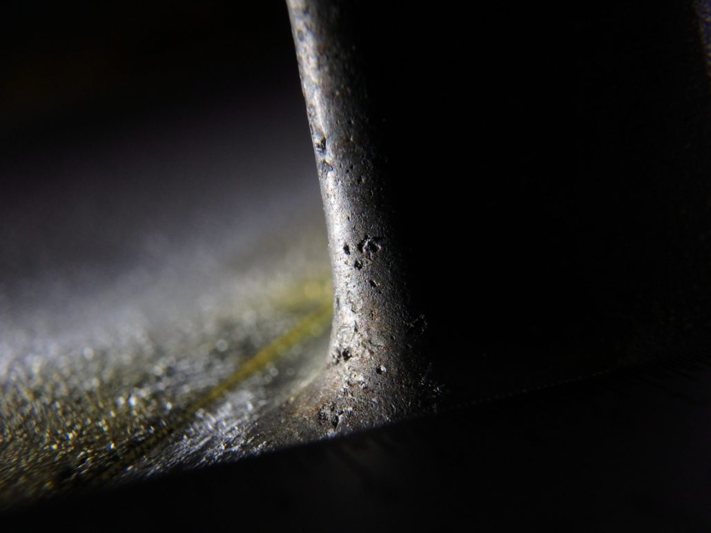
Figure 2. Forward compressor blade with leading edge pitting
On forward compressor blades and vanes, qualified inspectors have also observed combined effects of leading edge erosion and pitting. The erosion is typically the result of on-line water washing. The roughness of the eroded leading edge is now an ideal area for compressor deposits to become deeply embedded. Additionally, it serves as multiple stress concentrations for fatigue crack initiation.
The fall in compressor efficiency, the irreversible damage due to erosion and corrosion pitting, and the risk of catastrophic damage due to fracture initiation at the affected areas, all suggest that O&M staff need to have a strategy to mitigate compressor deposit accumulation, as well as erosion channeling. Additionally, the strategy should also consider the scenario where some deposit accumulation is unavoidable and how to reduce the activation of these deposits. Consideration should also be given to units that have a history of blade failures due to a design limitations that makes them susceptible to corrosion fatigue cracking. In such cases, the unit has a low tolerance to the presence of corrosion pitting for crack initiation.
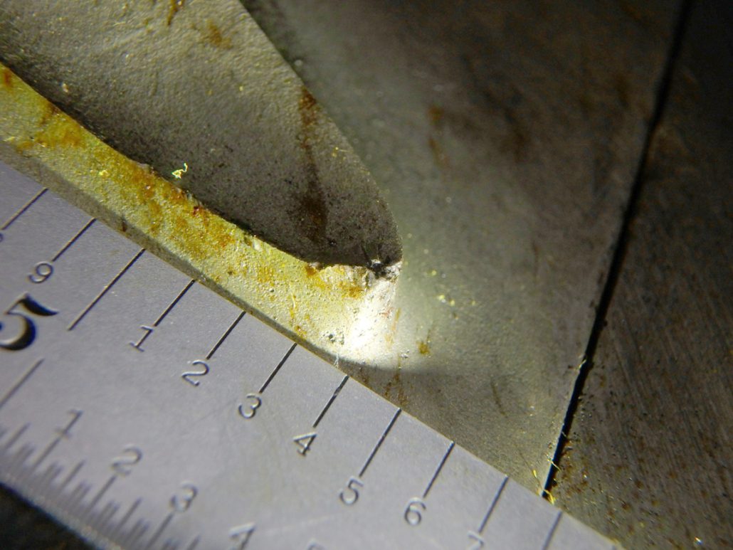
Figure 3. Fractured forward compressor blade with leading edge pitting at the origin
Typical Sources of Contamination – Land
Local geology and soil can contain large amounts of calcium, iron, magnesium, aluminum potassium, sodium, phosphorus, sulfur, as well as other less common species, including chlorides where the dry land used to be a sea bed. These elements are usually present as a compound, such as a mineral oxide or a salt, but may also be bound with organic material in the soil. Even with reasonably high efficiency filtration that removes 99.7% of the particulates within a given particle size range, the remaining 0.3% contamination multiplied by 1000lbs /hr of influent air results in a high rate of deposit accumulation. Deposits accumulated on airfoil surfaces can then liberate ionic species due to the absorption of moisture, thus creating a corrosion cell. Chlorides due to ubiquitous salts will rapidly corrode (pit) any and all of the stainless steels used in gas turbine compressors, with only partial mitigation by coatings. The only class of compressor materials reasonably immune to chloride or under deposit corrosion is the titanium alloy blades and vanes used in flight turbines and some aeroderivative units. Sulfur containing compounds are also commonly found on the airfoils of compressor blades and vanes, particularly in regions with heavy industry and refining. Sulfur containing compounds can also be extracted and diverted to the hot gas path cooling channels of downstream components, and greatly accelerate hot corrosion in the absence of moisture.
Atmosphere
The local quality of air entering the compressor is somewhat variable, and also dependent on geographic location. Coastal regions have an obvious problem with humid, chloride laden atmosphere. This particular environment is especially vulnerable to chloride pitting. Special inlet ducting and tailored filtration may provide some level of protection.

Figure 4. Fractured forward compressor blade with leading edge erosion at the origin
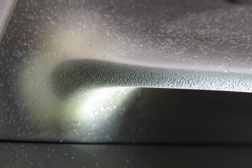
Figure 5. Forward compressor blade with leading edge erosion at platform radius
Local environments due to the proximity of inlets relative to cooling towers and the use of sodium hypochlorite for microbial control of cooling tower water can result in a chloride-laden influent to the unit. In this case the solution may be as simple as using a non-chloride based biocide for microbial control. In some cases the corrodents can come from non-typical activities at the plant, such as excursions of acid vapors from the water treatment facilities (sulfuric acid or hydrochloric acid).
Proximity to local industry, such as steel mills, coal or lignite fired boilers, oil production or refineries can result in a large influent concentration of sulfur bearing compounds. Sulfur bearing compounds, when incorporated into a deposit layer, can accelerate under-deposit corrosion and pitting, as well as aforementioned hot corrosion of downstream turbine components.
Water
Water source used for compressor washing (online and offline), as well as water used for power augmentation (misting, evaporative cooling, etc) should ideally be demineralized quality or better. The use of city water or another source of hard water is generally discouraged. Online water washing with a hard water source can result in increased deposit accumulation at and beyond the phase transition area (stage 2-5 typically) where the water boils to vapor and the dissolved minerals will deposit onto the blade /vane surfaces. Power augmentation by closed loop chiller systems also affords the opportunity for contamination due to leaks in the chilled fluid. These fluids can have variable water quality as well as chemicals added to the chiller loop. Non volatile constituents of the chilled water may leave deposits in a similar fashion as hard water. Evaporative cooling with hard water will result in mineral shedding that can accumulate downstream. As mentioned, on-line water washing will often cause leading edge erosion channeling, and more severely if the droplet size is not controlled, or leaking occurs during operation.
Historical Contaminants Observed in Compressor Deposits
Over the course of many years, we have been privileged to sample the deposits laden on blades and vanes from gas turbine units in many parts of the world. A pattern of contaminants (the usual suspects) has been observed, with some exceptions. The deposits observed are biased largely by one of the dominating contributors: Coastal conditions, land conditions, or local plant and industrial environment (neighboring industry or locally produced effluent).
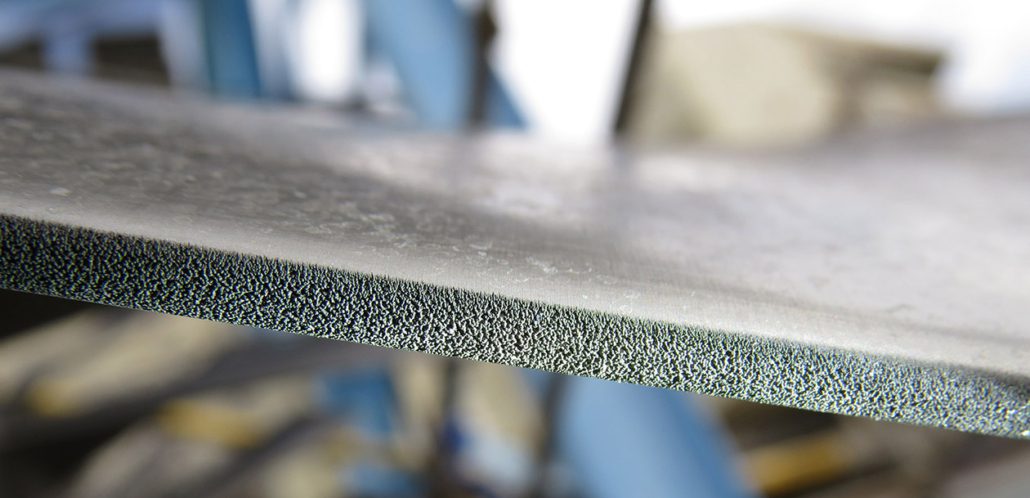
Figure 6. Forward compressor blade with leading edge erosion at airfoil mid span
Energy Dispersive Spectroscopy (EDS) provides qualitative elemental analysis of materials under scanning electron microscopy (SEM) examination based on the characteristic energies of x-rays produced by the electron beam striking a deposit sample. The relative concentrations of the identified elements are determined using semiquantitative, standardless quantification (SQ) software. This information can be used to tailor the filtration system and media, as well as the detergents used in compressor washing. It may also provide leverage for high level dialog with the local regulators and emitting sources.
Conclusions
The corrosion pitting on the compressor blades and vanes is almost always the result of under-deposit corrosion aggravated by the presence of corrosive species in the deposit. The corrosive species are often sulfur and chlorine-containing compounds, but pitting can also occur from simply the presence of oxygen under the deposit (oxygen pitting). The pitting is proof of corrosive deposits, and trace amounts of corrosive species identified by EDS at the bottom interface of the pits identifies the active corrodents so that treatment can be fine-tuned for that species.
The source of the corrodents can be local to the plant (cooling tower drift), in the soil, from the atmosphere (coastal chlorides) or from local industry (burning lignite or low grade coal, and / or oil and gas production). In some cases the corrodents can come from non-typical activities at the plant, such as the use of sodium hypochlorite (bleach) for biological control, or excursions of acid vapors from the water treatment facilities (sulfuric acid or hydrochloric acid). Plant operations can identify, address and mitigate the local sources.
Starts-based units, or peakers, also have life-limiting pitting that is difficult to understand without considering the effect of off-line corrosion. For units operating in cycling duty, a substantial amount of time is spent in idle mode. During idle periods, the unit is normally stationary or on turning gear for some daily period. After the rotor is ambiently cooled during the nightly lows, the rotor will retain much of the lower temperature relative to the increasing ambient temperature and humidity during the day. As a result the rotor will sweat like cold drink on a warm day, and the deposits on the blades and vanes will be similarly affected. This is a common mechanism for deposit activation and corrosion that seems to be aggravated by the new paradigm of unit cycling. These are the periods where corrosive deposits combined with moisture will create conditions ideal for pitting, particularly if the airfoil deposits contain a substantial concentration of sulfur and chlorine-containing compounds.
Mitigation
Units may be waterwashed online each day when operated and the ambient temperature is greater than about 50°F. Offline water washing may be performed prior to performance testing or to restore lost capacity. In both cases the water washing is performed to provide performance benefits and also to prevent the accumulation of corrosive deposits. However, performing an online waterwash prior to operation does not remove the deposits accumulated during the subsequent operation cycle, nor does it remove much deposit beyond the second stage due to phase transition from liquid to vapor. Moreover, if the subsequent operation cycle is followed by a long idle period in humid weather, the deposits can absorb the ambient moisture and activate the corrodents. Off-line washes must be performed with demineralized water and a cleaning solution tailored to the deposits. Proper rinses with conductivity measurements taken at the drain ports are advised. Offline water washing is much more effective at removing compressor deposit accumulation, but proper drying is necessary to prevent pitting under remaining, tenacious deposits.
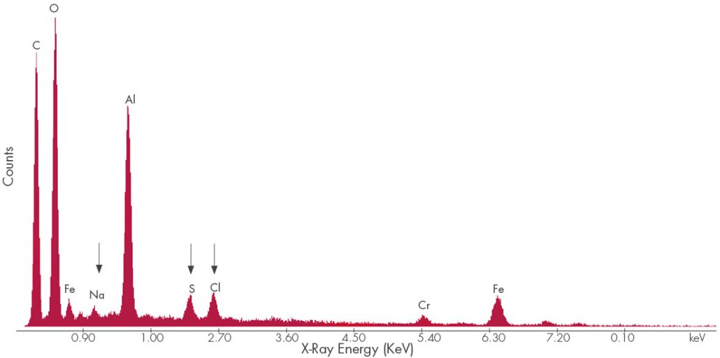
Figure 7. EDS Spectrum of compressor fouling deposits. Chlorides, sulfur deposits, and sodium deposits can be corrosive to stainless steels.
Another aspect of the operation that can affect the compressor deposits and moisture is proper sealing of the inlet filter house. All seams should be sealed with a weatherproof material and the fitment surfaces should be in good condition. Water leaks from the roof or any other area that causes standing water should be addressed. Additionally, corroded surfaces should be prepped and painted to stop the corrosion. Any bolts, nuts, and screws should be inspected for significant corrosion and potential loss of material that can become foreign object damage.
From a mitigation standpoint, two aspects must be addressed to reduce the susceptibility to pitting. First, the accumulation of deposits must be reduced. This may be achieved by higher efficiency filtration media (such as HEPA and hydrophobic Gore® Filters) and more aggressive offline water washing with a cleaning solution tailored to the deposits. Second, the presence of unwanted water must be reduced. Waterwashing should be followed by operation to ensure all moisture is evaporated. Water repelling filtration (such as Gore® filtration media) may reduce some of the water ingestion during wet weather, and may also prevent some of the influent from cooling tower drift (Gore® filtration medial is quite expensive, so a cost-benefit analysis may be require do to justify the additional expense). Long idle or layup periods should be combined with closure of the bellmouth and with a dry air source (heater or dehumidifier) to ensure that corrosive deposits are not activated. Mist eliminators and auto-close stack dampers are also beneficial, and should have some effect on reducing the ingress of moisture into the combustion turbine unit.
A detailed unit inspection may be advised, during which time deposit samples can be collected from the pre-filters, conical filters, and forward compressor blades / vanes / IGVs for corrosive species survey, as well as establishing the efficacy of the current filtration system. At this time, the severity of any pitting can also be documented. Additionally, mold replication can be performed on the LE of the forward compressor blades to gauge the severity of erosion channeling, which is often governed by OEM technical letters or service bulletins. A survey of the inlet filter house is also advised, where potential points of uncontrolled ingress can be identified. Additionally, the structure can be mapped for corrosion, cracked or damaged structures, and potential fastener liberation.
Jason Van Velsor, Robert Chambers
 The ability to continuously monitor component thickness at high temperatures has many benefits in the power generation industry, as well as many other industries. Most significantly, it enables condition-based inspection and maintenance, as opposed to schedule-based, which assists plant management optimizing operations and maintenance budgets and streamlining outage schedules. Furthermore, it can assist with the early identification of potential issues, which may be used to further optimize plant operations and provides ample time for contingency and repair planning.
Over the last several years, Structural Integrity has been working on the development of a real-time thickness monitoring technology that utilizes robust, unobtrusive, ultrasonic thick-film sensor technology that is enabling continuous operation at temperatures up to 800°F. Figure 1 shows a photograph of an installed ultrasonic thick-film array, illustrating the low-profile, surface-conforming nature of the sensor technology. The current version of this sensor technology has been demonstrated to operate continuously for over two years at temperatures up to 800°F, as seen in the plot in Figure 2. These sensors are now offered as part of SI’s SIIQ™ intelligent monitoring system.
Figure 1 – Photograph of an ultrasonic thick-film array for monitoring wall-thickness over a critical area of a component.
Figure 2 – A plot of ultrasonic signal amplitude over time for a sensor operating continuously at an atmospheric and component temperature of 800°F.
In addition to significant laboratory testing, the installation, performance, and longevity of Structural Integrity’s thick-film ultrasonic sensor technology has been demonstrated in actual operating power plant conditions, as seen in the photograph in Figure 3, where the sensors have been installed on multiple high-temperature piping components that are susceptible to wall thinning from erosion. In this application, the sensors are fabricated directly on the external surface of the pipe, covered with a protective coating, and then covered with the original piping insulation. Following installation, data can either be collected and transferred automatically using an installed data acquisition instrument, or a connection panel can be installed that permits users to periodically acquire data using a traditional off-the-shelf ultrasonic instrument.
Figure 4 shows two sets of ultrasonic data that were acquired approximately eight months apart at an operating power plant. The first data set was acquired at the time of sensor installation and the second data set was acquired after approximately eight months of typical cycling, with temperatures reaching up to ~500°F. Based on the observed change in the time-of-flight between the multiple backwall echoes observed in the signals, it is possible to determine that there has been approximately 0.005 inches of wall loss over the 8-month period. Accurately quantifying such as small loss in wall thickness can often provide meaningful insight into plant operations and processes, can provide an early indication of possible issues, and is only possible when using installed sensors.
Other potential applications of Structural Integrity’s ultrasonic thick-film sensor technology include the following:
In addition to novel sensor technologies to generate data, Structural Integrity offers customizable asset integrity management solutions, as part of the SIIQ platform, such as PlantTrackª, for storing and managing critical data. Many of these solutions are able to connect with plant historians to gather additional data that feed our engineering-based analytical algorithms, which assist in converting data into actionable information regarding plant assets. These algorithms are based on decades of engineering consulting and assessment experience in the power generation industry.
Reach out to one of our NDE experts to learn more about SI’s cutting-edge thick-film UT technology.
Figure 3 – Photograph showing Structural Integrity’s thick-film ultrasonic sensor technology installed on two high-temperature piping elbows that are susceptible to thinning from erosion.
Figure 4 – Ultrasonic waveforms acquired approximately 8 months apart showing 0.005 inches of wall loss at the sensor location over this period.
SIGN UP FOR OUR NEWSLETTER
*Join the conversation. Sign up to receive emails, events, and latest information!
1-877-4SI-POWER
(1-877-474-7693)
This site uses cookies. By continuing to browse the site, you are agreeing to our use of cookies.
OKLearn MoreWe may request cookies to be set on your device. We use cookies to let us know when you visit our websites, how you interact with us, to enrich your user experience, and to customize your relationship with our website.
Click on the different category headings to find out more. You can also change some of your preferences. Note that blocking some types of cookies may impact your experience on our websites and the services we are able to offer.
These cookies are strictly necessary to provide you with services available through our website and to use some of its features.
Because these cookies are strictly necessary to deliver the website, refusing them will have impact how our site functions. You always can block or delete cookies by changing your browser settings and force blocking all cookies on this website. But this will always prompt you to accept/refuse cookies when revisiting our site.
We fully respect if you want to refuse cookies but to avoid asking you again and again kindly allow us to store a cookie for that. You are free to opt out any time or opt in for other cookies to get a better experience. If you refuse cookies we will remove all set cookies in our domain.
We provide you with a list of stored cookies on your computer in our domain so you can check what we stored. Due to security reasons we are not able to show or modify cookies from other domains. You can check these in your browser security settings.
These cookies collect information that is used either in aggregate form to help us understand how our website is being used or how effective our marketing campaigns are, or to help us customize our website and application for you in order to enhance your experience.
If you do not want that we track your visit to our site you can disable tracking in your browser here:
We also use different external services like Google Webfonts, Google Maps, and external Video providers. Since these providers may collect personal data like your IP address we allow you to block them here. Please be aware that this might heavily reduce the functionality and appearance of our site. Changes will take effect once you reload the page.
Google Webfont Settings:
Google Map Settings:
Google reCaptcha Settings:
Vimeo and Youtube video embeds:
The following cookies are also needed - You can choose if you want to allow them:
You can read about our cookies and privacy settings in detail on our Privacy Policy Page.
